6
\$\begingroup\$

I am working with a flexiforce pressure sensor 25 lb.

I have to run 6 of them in parallel and I'm using an Arduino Uno. I'm not an electrical engineer (read: I'm a computer science major) and this is a school project. I am using a voltage divider for a single flexiforce to test the range and I don't know what the best fixed resistor value to use in order to get a larger range.

I am currently using a 200 Ohm resistor and am getting range from 0 to 30 (full range is to 1233)

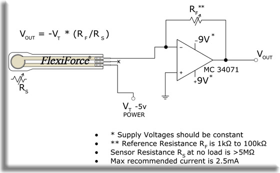
Here is there recommended circuit:

enter image description here

Using the Arduino, I can't make the amplifier thing or have a negative voltage input. Can someone please explain a way to get 6 of these sensors in an array with the highest sensitivity? Can I use a 9 V battery as an amplifier?

\$\endgroup\$

4 Answers 4

4
\$\begingroup\$

In this answer I showed that the optimal series resistor value is

\$ R_S = \sqrt{R_{MIN} \cdot R_{MAX}} \$

where \$R_{MIN}\$ and \$R_{MAX}\$ are the minimum and maximum resistances of your sensor. The Sparkfun page speaks of between infinity and 300 kΩ. If we assume 10 MΩ as maximum value then your series resistor should be 1.8 MΩ (rounded to nearest E12 value).

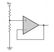
These are pretty high values, too high for an ADC, which, like Mathieu says, likes a impedance of less than 10 kΩ. So you'll need to buffer the divider with an unity gain buffer opamp:

enter image description here

Note that a common opamp may have an input bias current as high as 1 µA, and this could distort your reading. A CMOS opamp like the MCP600x has a much lower input bias current, 1 pA typical for the MCP600x, which won't deteriorate your reading.

\$\endgroup\$
2
\$\begingroup\$

Basically these sensors have a resistance that decreases as pressure is applied to their contact area. From what I can tell the decrease in resistance is a roughly hyperbolic (1/x) function of the force applied, and the change is basically from 5 MegOhms down to about 300 kOhms ("pressing hard" from the SF page).

If you use a 200 ohm resistor as the bottom leg of a voltage divider and this sensor as the top leg, I would predict you would see a range of approximately 0V with no pressure applied and 5 * 200 / (300e3 + 200) ~= 0.003. If you juiced up the 200 ohms up to say 300kOhms, I would expect your upper end to go up to about 2.5V. The bigger the upper resistor gets the closer your full scale gets to 5V, but the slower your response time will get because it's like you're charging/discharging a capacitor through a large resistances. It's also not going to do anything to linearize the sensor output for you.

The inverting amplifier configuration they suggest is based on the principal that the current flowing "into" the negative terminal of the op amp through the sensor will be equal and opposite to the current flowing "into" the negative terminal of the op amp. That is to say:

(V_n - V_T) / R_sense = (V_out - V_n) / R_F and V_n is driven to GND by the op-amp (so that the positive and negative terminals are at equal potential) so:

V_out = -V_T * R_F / R_sense = -V_T * R_F * (1 / R_sense)

We know that 1 / R_sense = conductance of the sensor is roughly linear with respect to the applied pressure from the user's guide (i.e. Pressure ~ 1 / R_sense, or Pressure = a * (1/R_sense) + b for some a and b) so:

V_out = -V_T * R_F * [(Pressure - b) / a]

This has the benefit of giving you an output voltage that is linear with respect to what you are sensing. Additionally, you can determine a and b through calibration at two (or more) fixed values. Finally you can adjust the range and slope of the output voltage by tuning R_F and/or V_T. The challenge then is that you need V_T to be negative with respect to your op amp supply voltage.

One way to accomplish this is would be a 9-volt battery with the positive terminal of the battery connected to GND of your op-amp and the negative terminal being V_T (effectively at -9V). You will then want to choose R_F so that you get an appropriate range of V_out per the above formulas. In tuning, V_out must not exceed the op-amp supply (probably 5V) or the amp will clip as well. There are more sophisticated ways of generating a negative voltage, for example by using another op-amp as an inverting buffer (as illustrated by U2 in this circuit which creates a virtual GND at the midpoint of the supply voltage), but I think the simpler approach should work of you, others can chime in if they disagree.

Long story short, I think you should follow their recommended circuit using the op-amp. You can get a DIP package with four rail-to-rail amps in it like this one, so with two of those chips, a 9V battery, and some resistors I think you've got everything you need.
\$\endgroup\$
1
\$\begingroup\$

See this link provided by CNMAT about maximizing the range with a voltage divider configuration.

Also important, for a good analog to digital conversion, the input impedance of the ADC should be no more than 10 kOhms. For this reason an op-amp (single supply, rail to rail) used as unity-gain buffer will improve the accuracy of your readings.

To maximize range, remember that you can also enable the external Analog Reference (Vref+) on the Arduino, see: http://arduino.cc/it/Reference/AnalogReference

See here for another possible analog front-end to use with FSRs: http://apollo.upc.es/humanoide/trac/wiki/PressureSensors

A note about using a transimpedance configuration is pickup noise, see "Layout considerations".

\$\endgroup\$
0
\$\begingroup\$

this seems like a simpler way to design sensor interface circuits:

http://www.eetimes.com/electronics-products/electronic-product-reviews/sensors-tranducers/4212510/Configurable-sensor-AFE-solution-aims-to-simplify-sensor-systems-designs--speeds-time-to-market

\$\endgroup\$
1
  • \$\begingroup\$ Whilst this may theoretically answer the question, it would be preferable to include the essential parts of the answer here, and provide the link for reference. \$\endgroup\$
    – Renan
    Commented Oct 29, 2012 at 0:39

Your Answer

By clicking “Post Your Answer”, you agree to our terms of service and acknowledge you have read our privacy policy.

Not the answer you're looking for? Browse other questions tagged or ask your own question.