0
\$\begingroup\$

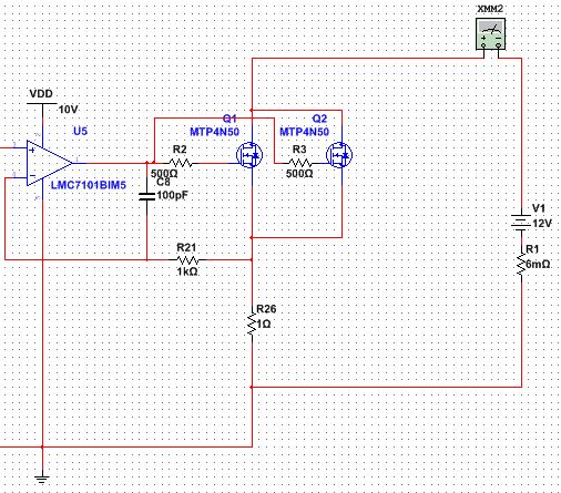
I have constant current source circuit as follow:

enter image description here

The mosfet chosen is: Fairchild Semiconductor FCH072N60F (Q1, Q2 are identical).

For anyone questioning the 500 Ohm gate resistance: I have to increase gate resistance to dampen MOSFET ringing (it gets pretty bad when Rg < 100).

My ultimate purpose is to generate a sinusoidal constant current (with Vpeak/2 DC offset) with this circuit. But for now, I use a 10V Vgs, 5A DC current for the sake of thermal analysis (input of the op amp is 5V DC). The phenomenon is the MOSFET is much hotter than the series resistance (R26). I think this suggests that Rds of the MOSFET are higher than 1 Ohm, which is not possible because the datasheet states that Rds = 0.06 Ohm to 0.07 ohm when Vgs = 10V.

I guess that the gate resistance Rg has something to do with this but changing Rg didn't help.

\$\endgroup\$
15
  • 1
    \$\begingroup\$ which is not possible because the datasheet states that Rds = 0.06 Ohm to 0.07 ohm when Vgs = 10V But is the Vgs = 10 V ??? I know that it is not (how do I know that ?). You expect 5 A to flow so for 12 V you'd need 12V / 5 A = 2.4 ohms. I only see 1 Ohm (R26, I'm ignoring R1). So what would make the 1.4 ohms you still need ?? \$\endgroup\$ Commented Nov 22, 2016 at 9:53
  • 1
    \$\begingroup\$ I know Vgs = 10V because I measured it. Assuming the circuit iw working, there is 5 V across R26, the opamp is fed by 10 V so the highest voltage at the output it can make is 10 V. So 10 V at the gates, 5 V at the sources: 10 - 5 V = 5 V. Maybe the gate potential is 10 V but that is not the same as Vgs. \$\endgroup\$ Commented Nov 22, 2016 at 10:10
  • 1
    \$\begingroup\$ Of course the MOSFETs are hot - what current are they taking and what voltage is across them!! \$\endgroup\$
    – Andy aka
    Commented Nov 22, 2016 at 10:12
  • 1
    \$\begingroup\$ Vds = 14.2 V How can that be when the supply is 12 V. If it is really 14.2 V then indicate that. Be accurate because it matters. \$\endgroup\$ Commented Nov 22, 2016 at 10:12
  • 3
    \$\begingroup\$ "Rds of the mosfet are higher than 1 Ohm, which is not possible [...]" Of course it is possible. You're in the linear region! \$\endgroup\$
    – dim
    Commented Nov 22, 2016 at 11:44

1 Answer 1

2
\$\begingroup\$

"Rds of the mosfet are higher than 1 Ohm, which is not possible..."

Consider: If you have a 12 volt supply connected from the MOSFET drain to the ground end of R26 (a one ohm resistor) and there's 5 amperes through R26, then there'll be 5 volts dropped across R26.

Now, since you started with 12 volts, what happened to the other 7 volts? There's only one reasonable answer, and that's that the 7 volts is being dropped across the MOSFET.

Then, since current in a series circuit is everywhere the same, that means there's 5 amperes through the MOSFET and, with 7 volts across it, it'll have an \$ {R_{DS}}\$ of

\$ R_{DS} =\frac{V_D-V_S}{I_D} = \frac {7V}{5A} = 1.4\text{ ohm} \$, and it'll be dissipating:

\$P = IE = 5A\times7V=35\text{ watts}\$.

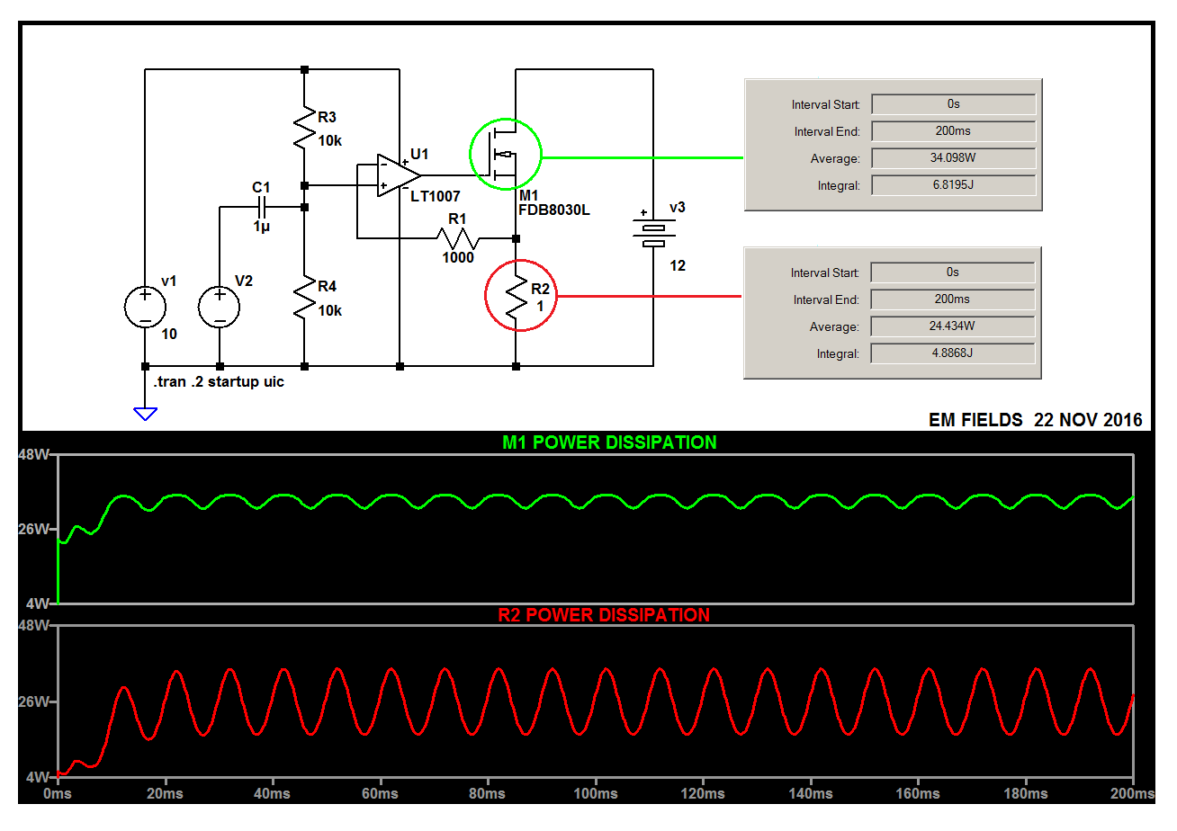
In the same vein, and just for grins, I simplified your circuit and added a little AC drive to see what it would do, and here's what I got:
enter image description here

Here's the LTspice circuit list so you can play with the circuit if you want to:

Version 4
SHEET 1 880 680
WIRE 48 0 -192 0
WIRE 192 0 48 0
WIRE 576 0 368 0
WIRE 48 48 48 0
WIRE 368 80 368 0
WIRE 192 128 192 0
WIRE 160 144 128 144
WIRE 320 160 224 160
WIRE 48 176 48 128
WIRE 160 176 48 176
WIRE -48 208 -80 208
WIRE 48 208 48 176
WIRE 48 208 16 208
WIRE 576 208 576 0
WIRE 128 256 128 144
WIRE 240 256 128 256
WIRE 368 256 368 176
WIRE 368 256 320 256
WIRE 48 304 48 208
WIRE 368 304 368 256
WIRE -192 320 -192 0
WIRE -80 320 -80 208
WIRE -192 448 -192 400
WIRE -80 448 -80 400
WIRE -80 448 -192 448
WIRE 48 448 48 384
WIRE 48 448 -80 448
WIRE 192 448 192 192
WIRE 192 448 48 448
WIRE 368 448 368 384
WIRE 368 448 192 448
WIRE 576 448 576 288
WIRE 576 448 368 448
WIRE -192 512 -192 448
FLAG -192 512 0
SYMBOL Opamps\\LT1007 192 96 R0
SYMATTR InstName U1
SYMBOL nmos 320 80 R0
SYMATTR InstName M1
SYMATTR Value FDB8030L
SYMBOL Misc\\battery 576 192 R0
WINDOW 123 0 0 Left 2
WINDOW 39 0 0 Left 2
SYMATTR InstName v3
SYMATTR Value 12
SYMBOL res 336 240 R90
WINDOW 0 0 56 VBottom 2
WINDOW 3 32 56 VTop 2
SYMATTR InstName R3
SYMATTR Value 1000
SYMBOL res 352 288 R0
SYMATTR InstName R4
SYMATTR Value 1
SYMBOL cap 16 192 R90
WINDOW 0 0 32 VBottom 2
WINDOW 3 32 32 VTop 2
SYMATTR InstName C1
SYMATTR Value 1µ
SYMBOL res 32 32 R0
SYMATTR InstName R1
SYMATTR Value 10k
SYMBOL res 32 288 R0
SYMATTR InstName R2
SYMATTR Value 10k
SYMBOL voltage -80 304 R0
WINDOW 3 24 96 Invisible 2
WINDOW 123 0 0 Left 2
WINDOW 39 0 0 Left 2
SYMATTR InstName V2
SYMATTR Value SINE(0 1 100)
SYMBOL voltage -192 304 R0
WINDOW 123 0 0 Left 2
WINDOW 39 0 0 Left 2
SYMATTR InstName V1
SYMATTR Value 10
TEXT -180 472 Left 2 !.tran .2 startup uic
\$\endgroup\$
6
  • \$\begingroup\$ Nice and clear explanation. If I may: I noticed that you often provide the whole LTspice source when a simulation is involved in your answers, which is nice for reproducing. But it is somewhat distracting. What I usually do in that case is providing a link to a pastebin page. \$\endgroup\$
    – dim
    Commented Nov 22, 2016 at 15:19
  • \$\begingroup\$ I think it's preferred, at this site, to put as much data as possible into the answer itself so that if the paste bin page dies, no harm done. I agree with that philosophy, and I always post the code as the last item so that it doesn't interfere with the presentation of the earlier text and graphic(s). Do you use LTspice? \$\endgroup\$
    – EM Fields
    Commented Nov 22, 2016 at 15:59
  • \$\begingroup\$ Thanks EM, I got it. Now to extend the power supply to about 270 V, the voltage drop on the mosfet would be 269V (R26 = 1 Ohm). Therefore, in order to have a sine current of peak 5A (with 2.5 A offset) across R26, mosfet's resistance must varies from 53.8 Ohm to its off state Rds. What is the method to find the suitable Mosfet for this scenario? \$\endgroup\$
    – HacLe
    Commented Nov 23, 2016 at 1:29
  • \$\begingroup\$ That's an entirely different question, and I don't mean to be rude, but it seems like you don't know what you're talking about. \$\endgroup\$
    – EM Fields
    Commented Nov 23, 2016 at 1:40
  • \$\begingroup\$ Good luck finding a MOSFET that can safely dissipate 1.3kW! \$\endgroup\$ Commented Nov 23, 2016 at 3:52

Your Answer

By clicking “Post Your Answer”, you agree to our terms of service and acknowledge you have read our privacy policy.

Not the answer you're looking for? Browse other questions tagged or ask your own question.