0
\$\begingroup\$

I'm attempting my first slightly more advanced circuit and failing. I have a led string which I'm powering with a 31V 0.21A power adapter that came with it. Now I'm trying to switch it on and off with a 2n2222 NPN transistor which I'm controlling with a Raspberry Pi 3.3V GPIO. Initially, I had an optocoupler in there also to keep my Raspberry safe but took it away to confirm it isn't the problem.

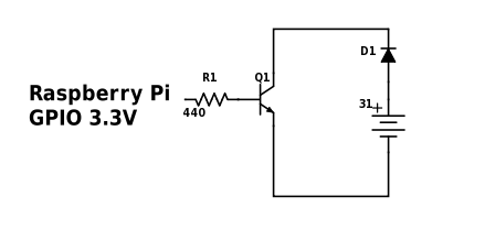
I have connected the emitter to ground, collector to the LEDs and the GPIO to base via two 220 resistors, achieving 440 ohms.

enter image description here

Now, putting the GPIO to high or low doesn't affect the lights (at least noticeably). Instead, the lights are steadily burning with a faint glow. Removing the GPIO from base pin turns off the lights completely. I'm having a hard time understanding what's going on.

Some questions that might solve this: I based my resistor calculations on this tutorial assuming 100 hFE. I'm not sure about the hFE value. The 2n2222 datasheet doesn't really tell what it is with 31V and 0.21A. Any help here?

The 31V is quite high (weird choice by the light manufacturer in my opinion) but the transistor can handle up to 40Vce and 1A. Am I misunderstanding something here?

One option is that I somehow got high and low the wrong way. Does the behavior sound like it could be caused by an inversed circuit?

Solution Thanks to @WillDean I realized I was using two grounds which was messing up a whole lot of things. I didn't realize this is an issue before the obvious was stated.

\$\endgroup\$
11
  • \$\begingroup\$ What LED string are you using? Also post pics and schematics please. Describing (and reading) connections with words is a bit difficult. \$\endgroup\$
    – Wesley Lee
    Nov 24, 2016 at 20:36
  • 1
    \$\begingroup\$ 100 is too high. For a normal (non-darlington) BJT it is normal to assume a hfe of 10 in order to ensure that the transistor is in saturation. \$\endgroup\$ Nov 24, 2016 at 20:41
  • \$\begingroup\$ @WesleyLee I added schematics. I don't know exactly what the led string is, I only know it's a 50 led string, 5 parallels of 10 series, that came with the adapter I described. \$\endgroup\$
    – Lof
    Nov 24, 2016 at 20:58
  • \$\begingroup\$ @IgnacioVazquez-Abrams That would leave me with something like a 40 ohm resistor according to my calculations. Sounds quite low? \$\endgroup\$
    – Lof
    Nov 24, 2016 at 21:00
  • 3
    \$\begingroup\$ Is your circuit ground (the battery -ve) actually connected to the Raspberry Pi ground? It makes no sense that putting the gpio to 'low' doesn't turn off the transistor but disconnecting it does. \$\endgroup\$
    – user1844
    Nov 24, 2016 at 21:11

1 Answer 1

3
\$\begingroup\$

You need to connect 0V of your RaPi to the emitter connection on your power supply because you cannot drive dc current into the base without a return path for that current.

But, before you do that make sure that the 31 V dc supply can connect to 0V on the RaPi safely i.e. is the 31 V supply isolated from ground?

It may be OK if it isn't but tread carefully because I don't want you to destroy your RaPi.

\$\endgroup\$

Your Answer

By clicking “Post Your Answer”, you agree to our terms of service and acknowledge that you have read and understand our privacy policy and code of conduct.

Not the answer you're looking for? Browse other questions tagged or ask your own question.