2
\$\begingroup\$

Sorry if this is a stupid question, but I'm in multiple electronics courses and I can't seem to understand input vs output impedance no matter who I ask.

I can always find the impedance between two points, if I am given the two points and I know all resistor/capacitor/inductor etc. values between those points along all possible paths between them. But when I'm asked to find input or output impedance of an entire circuit, I have no idea what those two points are. My professor seems to automatically understand which two points happen to correspond to input or output impedance in a given example, but to me, it seems completely arbitrary.

I understand that power supplies and loads have effective impedances, but often when I look at a circuit, I have no idea where the power supply ends and the load begins, or whether it's even relevant to think in terms of power supplies and loads... to me it's just a bunch of components jumbled together.

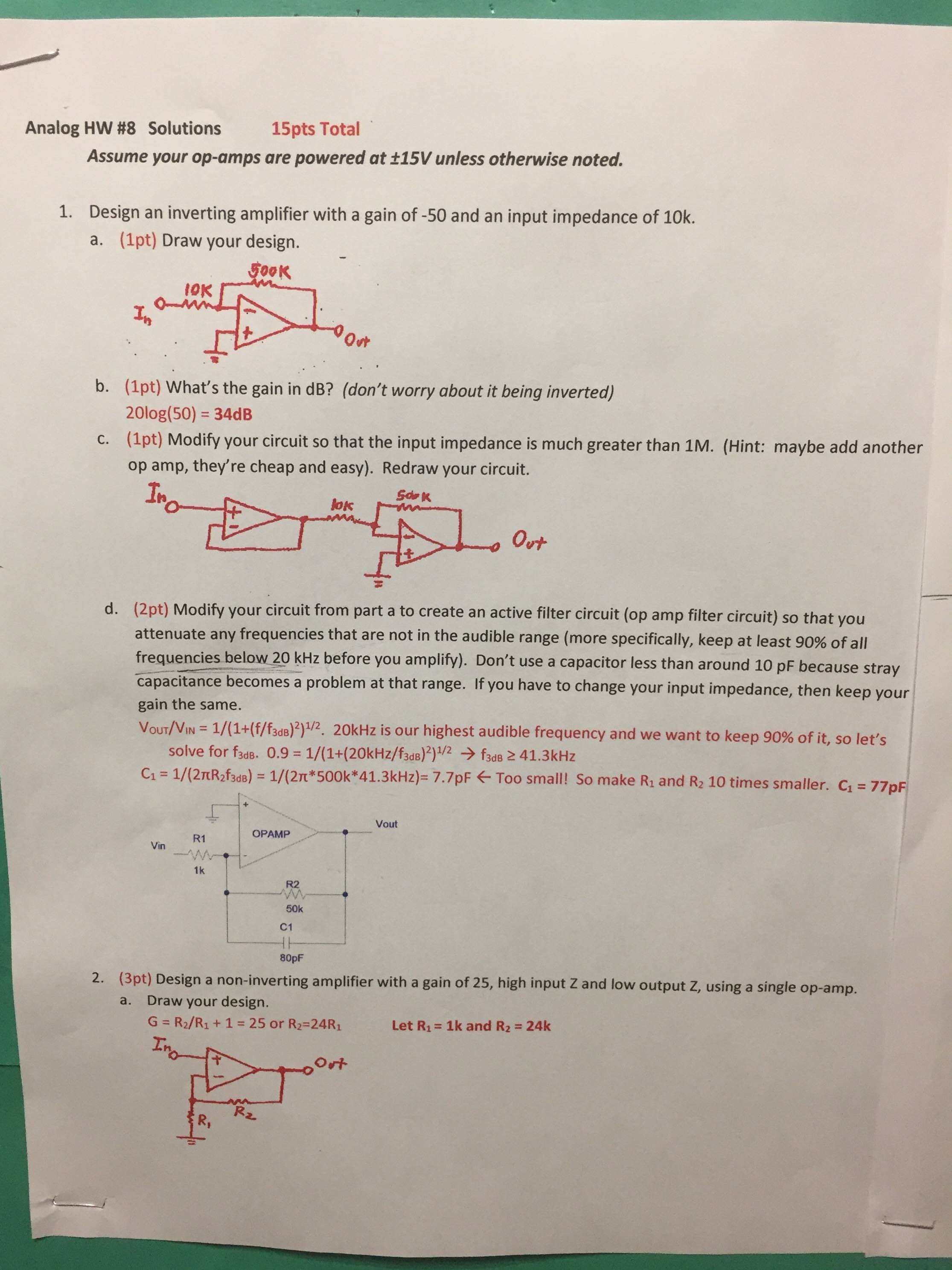
Here's some examples of worked homework problems (solutions in red):

worked homework example with solution in red

Why is it that the input impedance of the circuit in part "a" is 10k? Obviously there's a 10k resistor on the op amp input, which seems extremely simple, but it's also extremely vague. Why don't I need to worry about the 500k resistor? Why should I care that the input has a 10k resistor when the signal also runs into a 500k resistor and an op amp with an enormous resistance?

Then in part "c" we add another op amp to greatly increase the input resistance. Now all of a sudden we do care about the large op amp resistance, just because we put one op amp in front of another.

It really seems to be that simple, but I feel like I'm just saying "I'll just throw a 10k resistor in front of this circuit and voila, there's you 10k input resistance, have a nice day." If it's really that simple, I at least want to know why it's a helpful idea.

Could someone please break down this concept and really explain it to me like I have never seen electricity in my life. For some reason it's so obvious to others, that they do a terrible job of understanding just how confused I am, and their explanation won't help.

\$\endgroup\$
7
  • \$\begingroup\$ It sounds like you need to identify which point is the input? Surely this should be labelled? If not, it's traditional to put inputs on the left and outputs on the right. Could you give us a picture of an example please? \$\endgroup\$
    – pjc50
    Commented Dec 1, 2016 at 14:18
  • 1
    \$\begingroup\$ Question: "I have no idea what those two points are". Answer: It`s pretty simple: The input impedance is defined between the input node and the (common) ground! \$\endgroup\$
    – LvW
    Commented Dec 1, 2016 at 14:43
  • \$\begingroup\$ @LvW it's not that simple since a differential input contradicts your statement. Here Spehro talks about three different input impedances: electronics.stackexchange.com/questions/191487/… \$\endgroup\$
    – horta
    Commented Dec 1, 2016 at 14:48
  • \$\begingroup\$ @horta, I am aware that the input impedance at one port of a transistor-based diff. amplifier depends on the signal at the other port - however, I think that the questioner was asking for a "one-port" device. \$\endgroup\$
    – LvW
    Commented Dec 1, 2016 at 14:56
  • 1
    \$\begingroup\$ The key bit of your opamps course that I think you may have missed or underappreciated is the property that the opamp tends to drive both its input terminals to the same voltage (in most useful configurations), and therefore because the + terminal is connected to ground then you can treat the - as connected to ground as well (this behaviour is called virtual ground or virtual short). Think about that and I'll write an answer later. \$\endgroup\$
    – pjc50
    Commented Dec 1, 2016 at 16:37

2 Answers 2

2
\$\begingroup\$

pjc50 summed up the solution in comments.

Input impedance is defined as the impedance you would see no matter what the input voltage/current. With the fact that ideal op-amp analysis pins both inputs of the op-amp to the same voltage, and one of the inputs pinned to ground, the other terminal can be treated as a virtual ground. Now you have an infinite current source/sink at that virtual ground. That means if you create a test input voltage on the input side of the circuit, all it will see is 10k to "ground". 1V/10k=100uAmps. Input impedance is the test voltage divided by the resulting current so 1V/100uAmps = 10k. So that's how they're coming up with 10k as an input impedance.

If you wanted to determine the output impedance, you could look at the tail end and try and inject a 1V supply at the output side of the op-amp. The output of an op-amp can source or sink infinite current (pseudo-ground) so you basically have a connection from the output wire directly to ground. A wire directly to ground is 0 ohms so the output impedance in this case is 0 (or very low).

From what I can tell, your confusion comes then from not understanding how an ideal op-amp works. The input side of an op-amp tries to pin its two inputs to the same voltage and the output can source/sink infinite current to create the desired voltage.

\$\endgroup\$
2
  • \$\begingroup\$ That just gave me a revelation, and I even understand why I was so confused! The key to my confusion was that resistance doesn't have to be measured between 2 points; it can be measured by a single point that "sees" how difficult it is to travel in various directions! This is analogous to Cartesian vs polar coordinates. "Cartesian" requires two points to define resistance but is direction-independent, and "polar" requires one point but a direction-dependent magnitude. I was stuck in the "Cartesian" mode and I couldn't comprehend "polar" until now. \$\endgroup\$
    – Ryan Franz
    Commented Dec 1, 2016 at 23:19
  • \$\begingroup\$ @RyanFranz Right, single point measurements can be done with the assumption that the other "point" is general ground. And ground is nothing more than a reference voltage that is generally decided to be 0V. Glad it's making sense now! \$\endgroup\$
    – horta
    Commented Dec 2, 2016 at 15:10
0
\$\begingroup\$

OpAmp output impedance explains why OpAmps oscillate with various values of capacitive loads. You did ask about output impedance..

The standard (math) method is to inject Itest, perform the math, and determine a value(plus phase shift) for Vresult. This works for inputs and output.

In Zoutput of an OpAmp, there are 3 regions you can determine, given you insert a discrete resistor Rlump after the ideal voltage amplifier. We'll do this for a unity-gain circuit. 1) at very low frequencies (below the 10Hz rolloff of OpenLoopGain), Zout is Rout is Rlump/AVOL with phase of 0 degrees. 2) once the AVOL starts to roll off, Zout is Inductive. This inductor will resonate with an external Cload and ring or oscillate or produce overshoot on squarewave signals. To avoid all this, insert a resistor (try 33 ohms) between OpAmp output pin and the Cload. The proper value is computable, at least at lower frequencies where PCB and Via inductance need not be included. At a frequency 10X higher than where AVOL starts to roll off, the Zout will have increased by 10X above the DC value. But the phase-shift now enters the math. 3) above UGBW, right where you want the OpAmp to continue to provide LowPasFilter rollout, so you continue to get that 20dB/decade additional filtering, the Zout becomes unpredictably dependent upon the exact circuitry of the output transistors in the OpAmp. And dependent upon bipolar or MOS devices. If you do need that attenuation to continue past 0dB gain point, you'll need to include RC filters external to the OpAm.

\$\endgroup\$

Your Answer

By clicking “Post Your Answer”, you agree to our terms of service and acknowledge you have read our privacy policy.

Not the answer you're looking for? Browse other questions tagged or ask your own question.