18
\$\begingroup\$

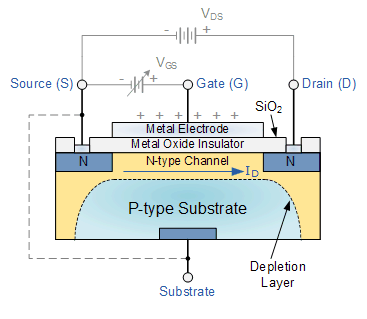
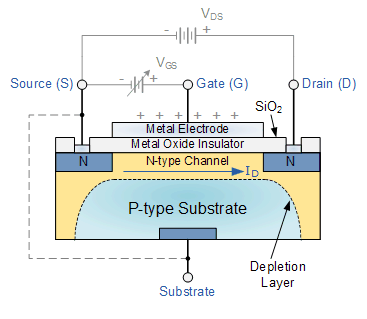
I know that , a basic MOSFET contains source and drain , and either it's a NMOS or PMOS ; it is indicated by an arrow at source . But let's look at a fabricated NMOS. enter image description here

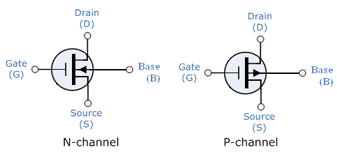
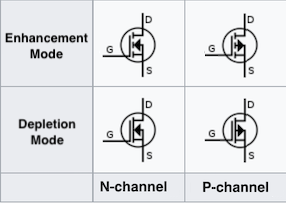
Here we can easily see that either a pin is source or drain is totally depended on the connection. Without connections , this device is symmetrical . But look at the conventional MOSFET symbols . enter image description here all these symbols marking a pin as source and other one as drain. Why is that ? Why this symbols are not symmetrical as the device is?

When I work on Cadence , schematics symbols all have this types of symbols where sources are marked .But when it will be used for fabrication , source and drain will be determined by the connection , not by the symbol.

\$\endgroup\$
4
  • 3
    \$\begingroup\$ See electronics.stackexchange.com/questions/72582/… \$\endgroup\$ Commented Dec 11, 2016 at 17:10
  • 1
    \$\begingroup\$ It isn't indicating the source with an arrow, it's indicating the substrate with an arrow. \$\endgroup\$
    – user20574
    Commented Dec 11, 2016 at 21:19
  • \$\begingroup\$ What is you plan for distinguishing between N and P channel devices if the arrow isn't there? \$\endgroup\$ Commented Dec 12, 2016 at 10:21
  • \$\begingroup\$ There are some symble where N and P channel indicatoin is given on gate, not on source or drain. noji.com/hamradio/img/CMOS-Symbols.png \$\endgroup\$
    – Anklon
    Commented Dec 12, 2016 at 13:37

5 Answers 5

15
\$\begingroup\$

IC MOSFETs aren't the same as their discrete counterparts

You are correct in that laterally diffused four-terminal MOSFETs (such as those that make up CMOS ICs) are symmetric devices -- the substrate or well is connected separately to the lowest or highest (depending on what kind of FET you have) potential in the circuit, while the source can be raised up above/lowered below the substrate/well potential.

However, 99% of the discrete MOSFETs made throughout history and 100% of the discrete MOSFETs in current production use a different structure -- instead of having the source and drain side-by-side, the drain is on the bottom and the source is on top, with the gate cut into the FET. This is called a vertical MOSFET, and is depicted below in its modern form (i.e. a trench MOS structure -- early vertical MOSFETs used a V-groove for the gate instead of the trench). These structures are inherently asymmetric, and also lend themselves to connecting to the substrate to the source, thus forming the body diode that is a surprisingly useful part of a power MOS device.

UMOS Illustration -- Wikipedia/Cyril Buttay

\$\endgroup\$
11
\$\begingroup\$

The arrow doesn't indicate the direction of current flow, it indicates the PN junction between the body and the channel.

If you use the 4-terminal symbol, it is in fact often symmetric: enter image description here

In IC design, design kits should give you the option to use these symbols or something like them, because the body will generally be tied to the lowest or highest potential on the entire IC (maybe with even more flexibility for PMOS devices in an n-well process), not necessarily to the same terminal as the source.

In discrete design, generally you're limited to connecting the body to the same terminal as the source.

\$\endgroup\$
9
\$\begingroup\$

Any P-N junction is a diode (among other ways to make diodes). A MOSFET has two of them, right here: enter image description here
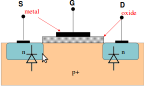
That big chunk of P-doped silicon is the body or the substrate. Considering these diodes, one can see it's pretty important that the body is always at a lower voltage than the source or the drain. Otherwise, you forward-bias the diodes, and that's probably not what you wanted.

But wait, it gets worse! A BJT is a three layer sandwich of NPN materials, right? A MOSFET also contains a BJT:
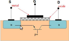
enter image description here

If the drain current is high, then the voltage across the channel between the source and the drain can also be high, because RDS(on)RDS(on) is non-zero. If it's high enough to forward-bias the body-source diode, you don't have a MOSFET anymore: you have a BJT. That's also not what you wanted.

In CMOS devices, it gets even worse. In CMOS, you have PNPN structures, which make a parasitic thyristor. This is what causes latchup.

Solution: short the body to the source. This shorts the base-emitter of the parasitic BJT, holding it firmly off. Ideally you don't do this through external leads, because then the "short" would also have high parasitic inductance and resistance, making the "holding off" of the parasitic BJT not so strong. Instead, you short them right at the die.

This is why MOSFETs aren't symmetrical. It may be that some designs otherwise are symmetrical, but to make a MOSFET that behaves reliably like a MOSFET, you have to short one of those N regions to the body. To whichever one you do that, it's now the source, and the diode you didn't short out is the "body diode".

This isn't anything specific to discrete transistors, really. If you do have a 4-terminal MOSFET, then you need to make sure that the body is always at the lowest voltage (or highest, for P-channel devices). In ICs, the body is the substrate for the whole IC, and it's usually connected to ground. If the body is at a lower voltage than the source, then you must consider body effect. If you take a look at a CMOS circuit where there's a source not connected to ground (like the NAND gate below), it doesn't really matter, because if B is high, then the lower-most transistor is on, and the one above it actually does have its source connected to ground. Or, B is low, and the output is high, and there isn't any current in the lower two transistors.
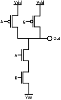
enter image description here

Collected from: MOSFET: Why the drain and source are different?

FYI: I'm too pleased with this detail answer that I thought this should be here. Thanks to Phil Frost
\$\endgroup\$
2
\$\begingroup\$

Source and drain are not always equal, this is true in particular for discrete devices, but there are also a number of integrated transistors with a different structure for source and drain.

Integrated transistors are very often symmetric, drain and source can be used interchangeably. The arrow at the "source" terminal is used to indicate the type of transistor (NMOS or PMOS) and it is used to properly map it onto underlying transistor models which are sometimes source-referenced. Of course the terminals can be used with drain and source exchanged and the transistor model is reversed.

Finally, there are some design kits where there is no source arrow to account for the fact that the transistors are symmetric.

\$\endgroup\$
1
\$\begingroup\$

Amongst the various correct and useful information presented here so far, is the answer. But no one has stated it explicitly, and confusion lingers. This is despite, I think, a very literal and intuitive interpretation being available. To wit:

all these symbols marking a pin as source and other one as drain. Why is that ?

Because they're 3-terminal symbols.

Let's start with your diagram:

MOSFET diagram

As you say, it is symmetrical, except for the dashed line. The light grey lines with the voltages are guidance only - they aren't related to the structure of the MOSFET.

The corresponding symbol is the (rare) 4-terminal symbol:

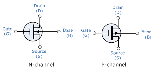
4-terminal MOSFET symbol

The N-channel symbol represents the MOSFET in the diagram. In a P-channel the N and P-type regions are swapped. Be careful with the term "base" - it's directly comparable to a BJT's base in terms of N and P-types, but different enough in practice that sticking with the MOSFET terms "substrate" or body is less confusing.

A key thing to observe at this point is that the arrow indicates the PN junction between the substrate and channel. In a BJT the arrow indicates the PN junction associated with the emitter, and thinking that the arrow in a MOSFET is associated with the source is a trap.

Now, this is still a symmetrical symbol and the source/drain labels are arbitrary. What happens if we draw the dashed line from the diagram on the symbol? The substrate gets connected to one of the terminals and we no longer need a dedicated substrate terminal. The device is no longer symmetric so we can specify which terminal is the source. What would the symbol look like if we dropped the substrate terminal and joined it to the source instead?

Maybe like this:

3-terminal MOSFET symbols

Well look at that - we've ended up at your original 3-terminal symbols, no tricks, no surprises. Okay, the fact the gate terminal no longer comes out of the middle of the device is a trick - three terminal MOSFETs do indeed tend to push the asymmetry further. The gate becomes more closely associated with the source than the drain, and the \$V_{GS}\$ differential is typically of more interest, so you often see this reflected in the position of the gate terminal in the symbol.

The 3-terminal devices are far more common in day-to-day use, so the 3-terminal symbol is also far more prevalent. But it helps to see it's structurally just the (symmetric) 4-terminal symbol, with the substrate connected internally.

\$\endgroup\$

Your Answer

By clicking “Post Your Answer”, you agree to our terms of service and acknowledge you have read our privacy policy.

Not the answer you're looking for? Browse other questions tagged or ask your own question.