10
\$\begingroup\$

I've been trying to design a module that will allow me to modify selected slave responses on an I2C bus. Here is the original bus configuration (the pull-ups and power connections are not shown for clarity:
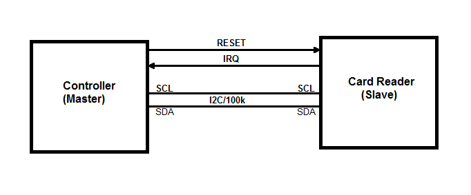
enter image description here There's only 2 devices on this bus and it's only 100kHz. A controller MCU (I2C master) and the RFID card reader (I2C slave) NXP PN512. I can't modify the controller firmware or change the I2C bus transactions. The good part is that the Controller sends only 2 types of transactions:

Master (Write Register) - <s><address+W><register number><data><p> Master (Read Register) - <s><address+W><register number><p><s><address+R><data><p>

What I want to do is to replace selected data bytes during the Master register read with my own bytes. I can send the register numbers the MCU wants to read to my PC over UART (921.6kbaud). I can process them in C/C++ or Python there. When I receive the register number whose value needs to be replaced I can send a fake byte back to my device and it will take care of sending it back to the controller replacing the original card response.

At first I split the I2C bus into two buses: enter image description here
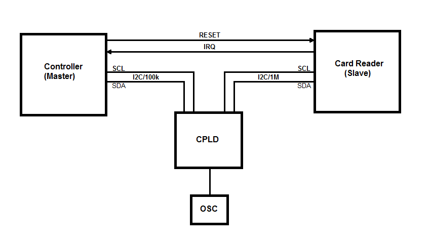
I tried Arduino Nano and later a CPLD using clock stretching. ATmega328 hardware I2C facing the MCU controller could not keep up as sometimes the start sequence was generated sooner than 5us after previous stop cycle. So every now and then the AVR was NAK'ing a read transaction. The CPLD could handle the stop/start speed it turned out the bus stretching was disabled in the MCU.

I came up with an idea that I can "predict" Master register read by detecting a single byte write since I'm sure that it's followed by a read. It seems that I had enough time during the following read cycle address write to bring in the byte from the slave. That did not quite work. The bus transactions seemed fine at the beginning (approx. first 5 seconds) but then the controller was ceasing all communications on the bus as if it detected that it's not directly talking to tag read.

The card reader can also generate interrupts to the master. The IRQs are a timer or event based. I attributed the problem to the delay I was inherently introducing on the bus. I might have been wrong but I came up with another "zero-delay" design. enter image description here
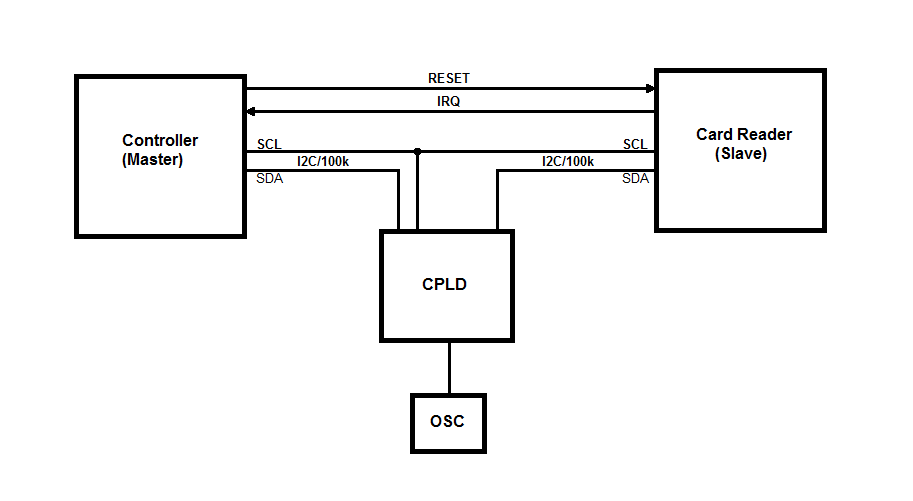
The idea is that I can only break the SDA line and leave the SCL line connected between the master and the slave. This way I can still replace bytes on the data line in either direction. The design proved to be more complicated as I have to control the SDA line direction based on the bus cycle. Here is the VHDL code that handles the bus transactions and sends hex bytes over UART to the computer. Receiving bytes from the computer is not yet implemented:

library ieee; 
use ieee.std_logic_1164.all; 
use ieee.numeric_std.all; 

entity I2C_Sniffer is 
port ( 
 clk : in std_logic;

 scl_master : in std_logic; 
 sda_master : inout std_logic;
 sda_slave  : inout std_logic;

 tx : out std_logic

); 
end entity I2C_Sniffer; 

architecture arch of I2C_Sniffer is
 signal clkDiv: std_logic_vector(7 downto 0) := (others => '0');

 type I2C_STATE is (I2C_IDLE, I2C_MASTER_WRITE, I2C_SLAVE_ACK, I2C_MASTER_READ, I2C_MASTER_ACK);
 signal i2cState: I2C_STATE := I2C_IDLE;

 type I2C_BUS_DIR is (MASTER_TO_SLAVE, SLAVE_TO_MASTER);
 signal i2cBusDir: I2C_BUS_DIR := MASTER_TO_SLAVE;

 signal i2cRxData: std_logic_vector(7 downto 0);
 signal i2cCntr: integer range 0 to 8 := 0;

 signal i2cAddr: std_logic := '1';
 signal i2cCmd: std_logic := '0';

 signal scl_d: std_logic := '1';
 signal scl: std_logic := '1';
 signal sda_d: std_logic := '1';
 signal sda: std_logic := '1';

 --Strobes for SCL edges and Start/Stop bits
 signal start_strobe : std_logic := '0';
 signal stop_strobe : std_logic := '0';
 signal scl_rising_strobe : std_logic := '0';
 signal scl_falling_strobe : std_logic := '0';

 type UART_STATE is (UART_IDLE, UART_START, UART_DATA, UART_STOP);
 signal uartState: UART_STATE := UART_IDLE;

 signal uartTxRdy: std_logic := '0';
 signal uartTxData: std_logic_vector(7 downto 0);
 signal uartCntr: integer range 0 to 8 := 0;

begin

 CLK_DIV: process (clk)
 begin
   if rising_edge(clk) then
     clkDiv <= std_logic_vector(unsigned(clkDiv) + 1);
   end if;
 end process;

I2C_STROBES: process (clk)
begin
  if rising_edge(clk) then
    --Pipelined SDA and SCL signals

    scl_d <= scl_master;
    scl <= scl_d;

    scl_rising_strobe <= '0';
    if scl = '0' and scl_d = '1' then
      scl_rising_strobe <= '1';
    end if;

    scl_falling_strobe <= '0';
    if scl = '1' and scl_d = '0' then
      scl_falling_strobe <= '1';
    end if;

    if i2cBusDir = MASTER_TO_SLAVE then
      sda_d <= sda_master;
      sda <= sda_d;
    else
      sda_d <= sda_slave;
      sda <= sda_d;
    end if;

    start_strobe <= '0';
    if sda_d = '0' and sda = '1' and scl = '1' and scl_d = '1' then
      start_strobe <= '1';
    end if;

    stop_strobe <= '0';
    if sda_d = '1' and sda = '0' and scl = '1' and scl_d = '1' then
      stop_strobe <= '1';
    end if;
  end if;
end process;

BUS_DIR: process(sda_master, sda_slave, i2cBusDir)
begin 
  if i2cBusDir = MASTER_TO_SLAVE then
    sda_slave <= sda_master;
    sda_master <= 'Z';
  else
    sda_master <= sda_slave;
    sda_slave <= 'Z';
  end if;
end process;

I2C: process(clk)
begin
    if rising_edge(clk) then
        uartTxRdy <= '0';

        case i2cState is
            when I2C_IDLE =>
                i2cBusDir <= MASTER_TO_SLAVE;

                if start_strobe = '1' then
                    i2cAddr <= '1';
                    i2cCntr <= 0;
                    i2cState <= I2C_MASTER_WRITE;
                end if;

            -- Master Write (Address/Data)
            when I2C_MASTER_WRITE =>
                i2cBusDir <= MASTER_TO_SLAVE;

                if stop_strobe = '1' then
                    i2cState <= I2C_IDLE;
                        uartTxData <= "00001010";
                        uartTxRdy <= '1';
                end if;

                if scl_rising_strobe = '1' then
                    if i2cCntr <= 7 then
                        i2cRxData(7 - i2cCntr) <= sda;
                        i2cCntr <= i2cCntr + 1;
                    end if;
                end if;

                if i2cCntr = 4 then
                    case i2cRxData(7 downto 4) is
                        when "0000" => uartTxData <= "00110000"; --0
                        when "0001" => uartTxData <= "00110001"; --1
                        when "0010" => uartTxData <= "00110010"; --2
                        when "0011" => uartTxData <= "00110011"; --3
                        when "0100" => uartTxData <= "00110100"; --4
                        when "0101" => uartTxData <= "00110101"; --5
                        when "0110" => uartTxData <= "00110110"; --6
                        when "0111" => uartTxData <= "00110111"; --7
                        when "1000" => uartTxData <= "00111000"; --8
                        when "1001" => uartTxData <= "00111001"; --9
                        when "1010" => uartTxData <= "01000001"; --A
                        when "1011" => uartTxData <= "01000010"; --B
                        when "1100" => uartTxData <= "01000011"; --C
                        when "1101" => uartTxData <= "01000100"; --D
                        when "1110" => uartTxData <= "01000101"; --E
                        when "1111" => uartTxData <= "01000110"; --F
                        when others => uartTxData <= "00111111"; --?
                    end case;
                    uartTxRdy <= '1';
                end if;

                if i2cCntr = 8 then
                    case i2cRxData(3 downto 0) is
                        when "0000" => uartTxData <= "00110000"; --0
                        when "0001" => uartTxData <= "00110001"; --1
                        when "0010" => uartTxData <= "00110010"; --2
                        when "0011" => uartTxData <= "00110011"; --3
                        when "0100" => uartTxData <= "00110100"; --4
                        when "0101" => uartTxData <= "00110101"; --5
                        when "0110" => uartTxData <= "00110110"; --6
                        when "0111" => uartTxData <= "00110111"; --7
                        when "1000" => uartTxData <= "00111000"; --8
                        when "1001" => uartTxData <= "00111001"; --9
                        when "1010" => uartTxData <= "01000001"; --A
                        when "1011" => uartTxData <= "01000010"; --B
                        when "1100" => uartTxData <= "01000011"; --C
                        when "1101" => uartTxData <= "01000100"; --D
                        when "1110" => uartTxData <= "01000101"; --E
                        when "1111" => uartTxData <= "01000110"; --F
                        when others => uartTxData <= "00111111"; --?
                    end case;
                    uartTxRdy <= '1';
                end if;

                if i2cCntr = 8 then
                    if scl_falling_strobe = '1' then
                        i2cState <= I2C_SLAVE_ACK;

                        if i2cAddr = '1' then
                            i2cCmd <= i2cRxData(0);
                            i2cAddr <= '0';
                        end if;
                    end if;
                end if;

            when I2C_SLAVE_ACK =>
                i2cBusDir <= SLAVE_TO_MASTER;

                if scl_falling_strobe = '1' then
                    i2cCntr <= 0;

                    if i2cCmd = '0' then
                        i2cState <= I2C_MASTER_WRITE;
                    else
                        i2cState <= I2C_MASTER_READ;
                    end if;
                end if;

            when I2C_MASTER_READ =>
                i2cBusDir <= SLAVE_TO_MASTER;

                if stop_strobe = '1' then
                    i2cState <= I2C_IDLE;
                        uartTxData <= "00001010";
                        uartTxRdy <= '1';
                end if;

                if scl_rising_strobe = '1' then
                    if i2cCntr <= 7 then
                        i2cRxData(7 - i2cCntr) <= sda;
                        i2cCntr <= i2cCntr + 1;
                    end if;
                end if;

                if i2cCntr = 4 then
                    case i2cRxData(7 downto 4) is
                        when "0000" => uartTxData <= "00110000"; --0
                        when "0001" => uartTxData <= "00110001"; --1
                        when "0010" => uartTxData <= "00110010"; --2
                        when "0011" => uartTxData <= "00110011"; --3
                        when "0100" => uartTxData <= "00110100"; --4
                        when "0101" => uartTxData <= "00110101"; --5
                        when "0110" => uartTxData <= "00110110"; --6
                        when "0111" => uartTxData <= "00110111"; --7
                        when "1000" => uartTxData <= "00111000"; --8
                        when "1001" => uartTxData <= "00111001"; --9
                        when "1010" => uartTxData <= "01000001"; --A
                        when "1011" => uartTxData <= "01000010"; --B
                        when "1100" => uartTxData <= "01000011"; --C
                        when "1101" => uartTxData <= "01000100"; --D
                        when "1110" => uartTxData <= "01000101"; --E
                        when "1111" => uartTxData <= "01000110"; --F
                        when others => uartTxData <= "00111111"; --?
                    end case;
                    uartTxRdy <= '1';
                end if;

                if i2cCntr = 8 then
                    case i2cRxData(3 downto 0) is
                        when "0000" => uartTxData <= "00110000"; --0
                        when "0001" => uartTxData <= "00110001"; --1
                        when "0010" => uartTxData <= "00110010"; --2
                        when "0011" => uartTxData <= "00110011"; --3
                        when "0100" => uartTxData <= "00110100"; --4
                        when "0101" => uartTxData <= "00110101"; --5
                        when "0110" => uartTxData <= "00110110"; --6
                        when "0111" => uartTxData <= "00110111"; --7
                        when "1000" => uartTxData <= "00111000"; --8
                        when "1001" => uartTxData <= "00111001"; --9
                        when "1010" => uartTxData <= "01000001"; --A
                        when "1011" => uartTxData <= "01000010"; --B
                        when "1100" => uartTxData <= "01000011"; --C
                        when "1101" => uartTxData <= "01000100"; --D
                        when "1110" => uartTxData <= "01000101"; --E
                        when "1111" => uartTxData <= "01000110"; --F
                        when others => uartTxData <= "00111111"; --?
                    end case;
                    uartTxRdy <= '1';
                end if;

                if i2cCntr = 8 and scl_falling_strobe = '1' then
                    i2cState <= I2C_MASTER_ACK;
                end if;

            when I2C_MASTER_ACK =>
                i2cBusDir <= MASTER_TO_SLAVE;
                if scl_falling_strobe = '1' then
                    i2cCntr <= 0;
                end if;

                if stop_strobe = '1' then
                    i2cState <= I2C_IDLE;
                    uartTxData <= "00001010"; -- \n
                    uartTxRdy <= '1';
                end if;
        end case;
    end if;
end process;


UART: process (clk, clkDiv(1), uartTxRdy)
begin
    if rising_edge(clk) then
        case uartState is
            when UART_IDLE =>
                if uartTxRdy = '1' then
                    uartState <= UART_START;
                end if;

            when UART_START =>
                if clkDiv(1 downto 0) = "00" then
                    tx <= '0';
                    uartState <= UART_DATA;
                    uartCntr <= 0;
                end if;

            when UART_DATA =>
                if clkDiv(1 downto 0) = "00" then
                    if uartCntr <= 7 then
                        uartCntr <= uartCntr + 1;
                        tx <= uartTxData(uartCntr);
                    else
                        tx <= '1';
                        uartState <= UART_STOP;
                    end if;
                end if;

            when UART_STOP =>
                if clkDiv(1 downto 0) = "00" then
                    tx <= '1';
                    uartState <= UART_IDLE;
                end if;
        end case;
    end if;
  end process;
end architecture arch;

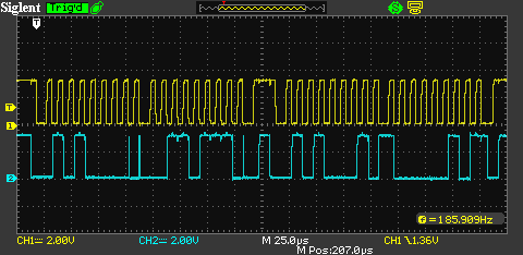
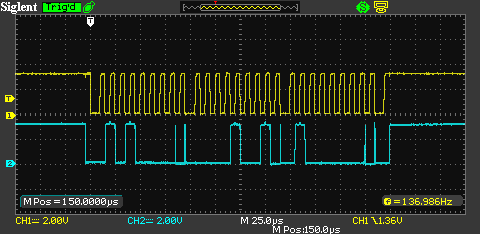
Below are the bus transations captured with the CPLD controlling the SDA line.

Register write:

enter image description here

Register read:

enter image description here

You can see a few glitches when the bus direction changes. That's caused by the differences in timing between the CPLD changing the bus direction and the card reader generating an ACK. The ACK level seems to be stable on the rising edge of the SCL. As far as I know that's all you need.

With this thing in place the controller behaves the same way as with the split buses suspending any bus activity within a few seconds. I also test that w Arduino that mocks that MCU and generates bus traffic for me and it looks like Arduino also freezes every now and then. So I guess I may have some kind of issue with the VHDL state machine where under some conditions I get stuck in one state with no way out. Any ideas?

\$\endgroup\$
9
  • \$\begingroup\$ Your question isn't very clear, to me anyways. First you say There's only 2 devices on this bus running at 100kHz and then The hardware I2C was a slave and a bit banged I2C was a master on the card reader bus at 1Mbps. Why are there two buses? Why the need for the high speed bus? Provide a sketch of your initial design and try to clarify your question. \$\endgroup\$ Dec 13, 2016 at 22:02
  • \$\begingroup\$ Yeah, sorry. The original bus only has the controller (i2c master) and the RFID card/tag reader (i2c slave). Therefore I don't really have to worry about I2C addressing as it's point-to-point (every packet sent by the master is for this one slave). My first approach was to split the bus into 2 buses and act as i2c slave on the controller side and a master on the RFID reader side. \$\endgroup\$
    – Alexxx
    Dec 14, 2016 at 14:28
  • \$\begingroup\$ The RIFD reader is capable of faster speeds (1MHz or even faster) so I thought I may as we use that so I don't hold the bus (bus stretching) on the controller side for too long while I read data from the RFID reader register. Also, without the bus stretching when I detect a single byte write I only have little time during the next read cycle to read the byte from the RIFD reader and send it back to the controller. \$\endgroup\$
    – Alexxx
    Dec 14, 2016 at 14:34
  • \$\begingroup\$ By bus streching I mean the I2C clock stretching where the slave holds the SCL line low to let the master know that it's not yet ready for with the data. When the slave is ready it releases the SCL line and the master continues to read the bits sent by the slave. \$\endgroup\$
    – Alexxx
    Dec 14, 2016 at 14:46
  • 1
    \$\begingroup\$ It's best if you edit your question instead. You still haven't explained why 2 buses are needed. If all you need is to read data from the card reader employing I2C then why not just connect them on the same bus and have your MCU read from it? Clock stretching only makes sense on the slave's side, usually when its slow to respond to a master. Theres nothing you can do about it if the slave isnt ready. 100-400kHz is usually enough for most applications; the only reason you might want faster speeds if you must perform some time-sensitive operation on the data you've read or similar. \$\endgroup\$ Dec 14, 2016 at 15:18

2 Answers 2

8
+50
\$\begingroup\$

I think that attempting cutsey hacks like you have been is asking for trouble, with exactly the kind of symptoms you are running into. You are basically trying to cheat and hope you don't get caught.

The one thing you haven't tried, according to your description, is a full emulation of this card reader thing. You haven't really explained what exactly it does and how complicated it is, but judging from what the master is sending it's not that complicated.

Use a microcontroller with hardware IIC slave capability. That is connected to the master. The firmware emulates the card reader. Since the only thing the master ever reads is a sequence of registers, the other part of the firmware communicates completely asynchronously with the card reader to get information from it and to control it. This also means that the reset and IRQ lines are separate too.

If done right, this has to work, as there is no cheating going on. The card reader sees a controller sending it commands and doing reads exactly how it was intended to be used. This includes responding to IRQ events.

The master thinks it's talking directly to a real card reader because you emulate all its operations just like the real thing, including the reset and IRQ behavior.

This may sound like more work than some quick and dirty jamming a different byte onto the bus hack, but as you found that's not so quick, and may always have some timing issues. With a full emulation, all timing constraints are lifted. If your emulation hasn't yet caught up to something the card reader has done, then it acts to the master like it hasn't happened yet. You basically pretend nothing new has happened until your emulation is ready to respond to the event in all aspects.

This means you really have two asynchronous parts of the firmware: The IIC emulation of the reader presented to the master, and a full card reader driver that allows you to keep all its state live in your internal memory.

Since you're not cheating, this has to work if done right. The only system-level issue is that there will be some delay in the master seeing and causing card reader actions than the existing system. This doesn't sound like a big deal for a "card reader", and considering this delay would likely be 10s of milliseconds at worst. It certainly should not be noticeable on a human time scale.

Note that the communication between your emulator and the card reader isn't limited to the 100 kbits/s currently used. You should run that as fast as the card reader and your hardware allows. After all, on that link you'll be the master, so you own the clock. Again, with proper firmware architecture and asynchronous tasks, this should not matter. In fact, your driver will probably communicate more often and get more data from the card reader than the master gets from your emulator.

\$\endgroup\$
2
  • \$\begingroup\$ Thanks for the answer. I exactly had the some in mind when I first stated looking at that. I quickly abandoned the idea as that seems to be quite complicated. If the MCU was only writing and reading the registers it'd be easy but the reader communicates with an RFID which has its own protocol (multi-byte commands and responses). On top of that the MCU is setting up a few flags for the IRQ in the reader and reading back statues. Therefore it seemed like it would be lot easier to only target a few bytes and leave the rest to the reader. \$\endgroup\$
    – Alexxx
    Dec 15, 2016 at 23:25
  • \$\begingroup\$ Also, if I split the entire bus into 2 buses I indeed can talk to the card reader at faster speeds. However with the latest design where I cut the SDA line only I have to stick to the timing provided by the MCU on the SCL line which is 100KHz. \$\endgroup\$
    – Alexxx
    Dec 15, 2016 at 23:33
1
\$\begingroup\$

I'd suggest you were on the right track with an Arduino Nano as the MITM, though I think it would be best with two.

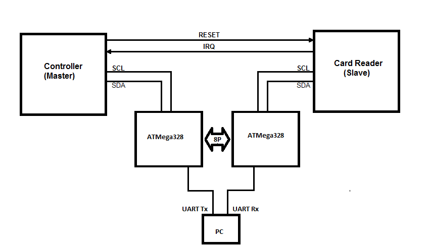
enter image description here

The NXP-PN512 will run at 3.4 Mhz clock speed, so I'd suggest you could use something of the order of 1.5 - 2 MHz for the right hand MCU talking to the Reader.
Since the left hand MCU is set at 100 kHz, once you have recognized any transaction bytes (address/register-W-R) you can copy it over an 8bit parallel bus (or even wider) between the MCU's and send the commands to the reader in less than one clock time on the slow speed I2C channel. Equally receiving a byte from the reader is achieved in less than a clock time on the slow bus giving adequate time to setup the reply byte.

I'm assuming here that you may actually need to translate multiple bytes as an NFC ID and not just a single byte by byte conversion (which requires less time).

The major problem I'd see then is that if you do need to serialize multiple bytes to/from the PC to map your changes, timing becomes even more critical. If there was a way to build your mapping change algorithm/table into the left hand MCU that would seem a better approach, though solving a multi-bye identifier mapping is still the biggest challenge.

If I'm wrong and you just need to map say a single card identifier byte, then this might work.

In your early testing with the Arduino, did you ensure that all interrupts were turned off (at least only TWI being used)? If you did not then this may have messed with your timing.

\$\endgroup\$
6
  • 1
    \$\begingroup\$ I don't see why two separate micros are necessary. Plenty of micros can handle two IIC busses simultaneously. You really only need hardware for being the slave, although using hardware can be convenient even when being the master. Communicating between two micros seems unnecessarily complex and slow, compared to two tasks running in the same micro. I fail to see the problem that two micros solve. \$\endgroup\$ Dec 22, 2016 at 18:55
  • \$\begingroup\$ @Olin Lathrop. It simplifies software development. makes debugging much simpler etc etc. It's like why do cars have 100's of microprocessors in them rather then one (simpler as you might suggest) large multiprocess processor. I have absolutely no problem using multiple MCU's where the cost is mostly below that of single function logic chips and the functionality is easier to define and develop. In this case there is only one TWI interrupt vector in the ATMega328 so to support two channels of I2C is harder. ..But it's certainly a personal choice. \$\endgroup\$ Dec 22, 2016 at 19:02
  • \$\begingroup\$ In this case, multiple processors adds complexity and introduces a need for extra communication. You don't need to use interrupts, or hardware at all, for IIC when you're the bus master. However, there are plenty of processors that can handle two IIC busses independently in hardware. If the ATMega can't, and you want to use two hardware IIC, then don't use a ATMega. \$\endgroup\$ Dec 22, 2016 at 19:40
  • \$\begingroup\$ @Olin Lathrop. Let's agree to disagree. IMO bit bashing above a hundred kHz is a non-starter. The problem for the OP is that the cost of serializing data to send to a PC to do the mapping algorithm is fraught with timing issues. \$\endgroup\$ Dec 22, 2016 at 20:06
  • \$\begingroup\$ Thanks for the answer and comments. ATMega328/Arduino cannot be used on the MCU side because of the MCU I2C timing. This MCU is capable of generating a start sequence faster than 4.7us after a previous stop. Look at table 32-10 in the ATMega328 datasheets (tBUF parameter). What was happening was that Arduino was NACKing all i2c reads that followed a i2c write. It's apparently a known issue. I found info on that somewhere online after I pulled all my hair over this. This is why I switched to the CPLD. \$\endgroup\$
    – Alexxx
    Dec 23, 2016 at 12:14

Your Answer

By clicking “Post Your Answer”, you agree to our terms of service and acknowledge that you have read and understand our privacy policy and code of conduct.

Not the answer you're looking for? Browse other questions tagged or ask your own question.