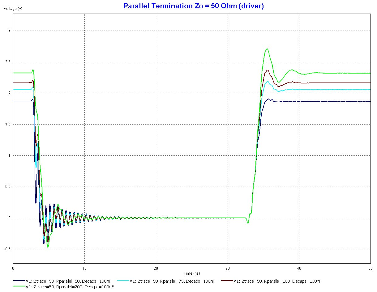
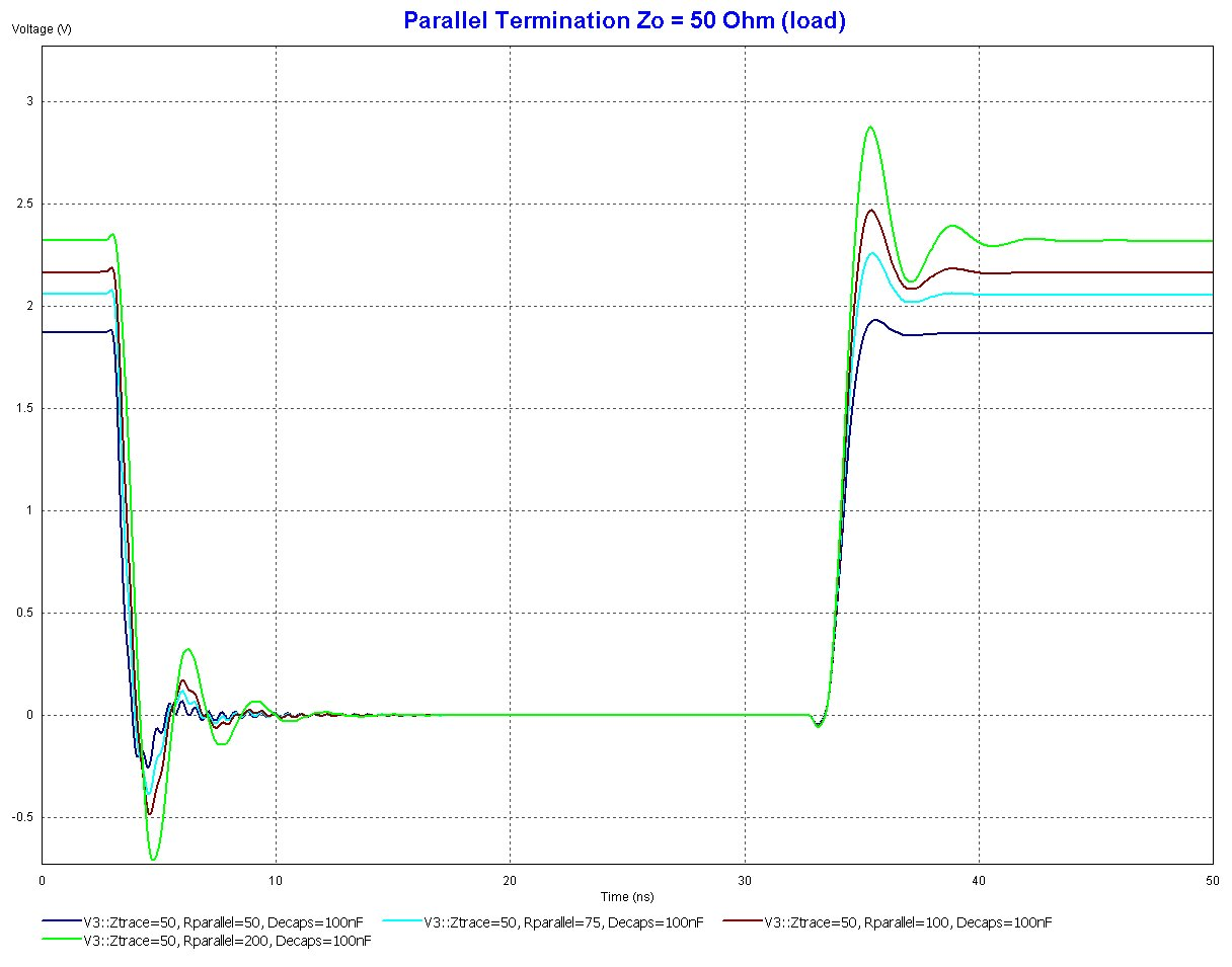
I have seen that when terminating an RS422 point-to-point connection, you should terminate the signals with a parallel resistor that matches the characteristic impedance of the transmission line. Most sources recommend 100-120ohms. I saw another post here that mentioned the effects of using too small of a terminating resistor, but what happens if you use a terminating resistor that is double, or 10 times the value of the characteristic impedance of the line?
-
\$\begingroup\$ Are you familiar with the problem that termination resistors solve and why they solve it? \$\endgroup\$– Cort AmmonCommented Dec 15, 2016 at 0:38
-
\$\begingroup\$ I realize matching the termination resistor to the Zo of the line should eliminate reflections. I have read that a resistor value lower than Zo will only eliminate a portion of the reflection. The part I'm having trouble with is when the resistor is greater than Zo. I guess it would still have the same effect, but the reflection would have the opposite polarity? \$\endgroup\$– cjswishCommented Dec 15, 2016 at 15:24
3 Answers
On an open end, a short pulse will be reflected and travel back the line.
On a shorted end, a short pulse will also be reflected, but inverted, too.
A resistor dampens this effect, i.e. the amplitude of the reflected signal will be smaller. And for a certain value, the pulse will not be reflected at all. This is the value used for termination.
Usually, transmitted signals are not short enough to be reflected completely, but every edge would cause a reflected pulse, which causes all kinds of trouble.
See also What and Why's of termination?
-
\$\begingroup\$ Thanks for the link. That is a great explanation of signal reflections! I have been working in the industrial rotary encoder field and, as you can imagine, this is a big deal. Most applications involve pulse rates of up to 1MHz and line lengths of several hundred ft. \$\endgroup\$– cjswishCommented Dec 15, 2016 at 15:29
If the resistor is too large, you will get incomplete damping of the fast edges of the signal, resulting in increased "ringing" and longer settling times.
This recent question mentions a way of estimating this graphically.
Infineon's application note EMC and System-ESD Design Guidelines for Board Layout has simulations for various parallel termination resistors, which show that you'd get more ringing:


