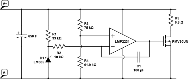
I am interested in charging a supercapacitor from a solar panel. I saw a circuit on this page by David Johnson. He doesn't let you copy the circuit, but the gist of it is this:

simulate this circuit – Schematic created using CircuitLab
I understand most of this. The op-amp is acting as a comparator for V+ through a voltage divider, so that when V+ is 2.654V it will reach the comparator threshold of 1.2V (the LM385 is a 1.2V reference).
(2.654 * 61.9) / (75 + 61.9) = 1.2
When the input voltage exceeds 2.654V the op-amp will turn on the MOSFET which will conduct R5 to V-, thus shunting the input voltage to stop it exceeding 2.654V (by much). (The super-capacitor in this case is a 2.7V one).
I have two questions:
What is C1 for? I presume stability of the op-amp, but am not sure.
What is R2 for? That doesn't seem to be doing much. It isn't acting as a voltage divider, and the op-amp input is already high-impedance. I am guessing it is something to do with circuit stability, but am not sure. What is to stop you connecting the voltage reference directly to the non-inverting input of the op-amp? Why choose 10k and not some other value?
