2
\$\begingroup\$

I have bought a phono-preamp stage from Audio Technica, and the output is quite low. (Using a MM cartridge.) I managed to retrieve a data-sheet which shows how the circuit is laid out. Phono Pre-Amp Circuit I'm not entirely sure how to proceed. The setup seems to be a fairly standard non-inverting OP-Amp setup. The Equalization appears to happen in the feeback. I initially thought R28/R18 were responsible for the gain but that doesn't seem to be the case.
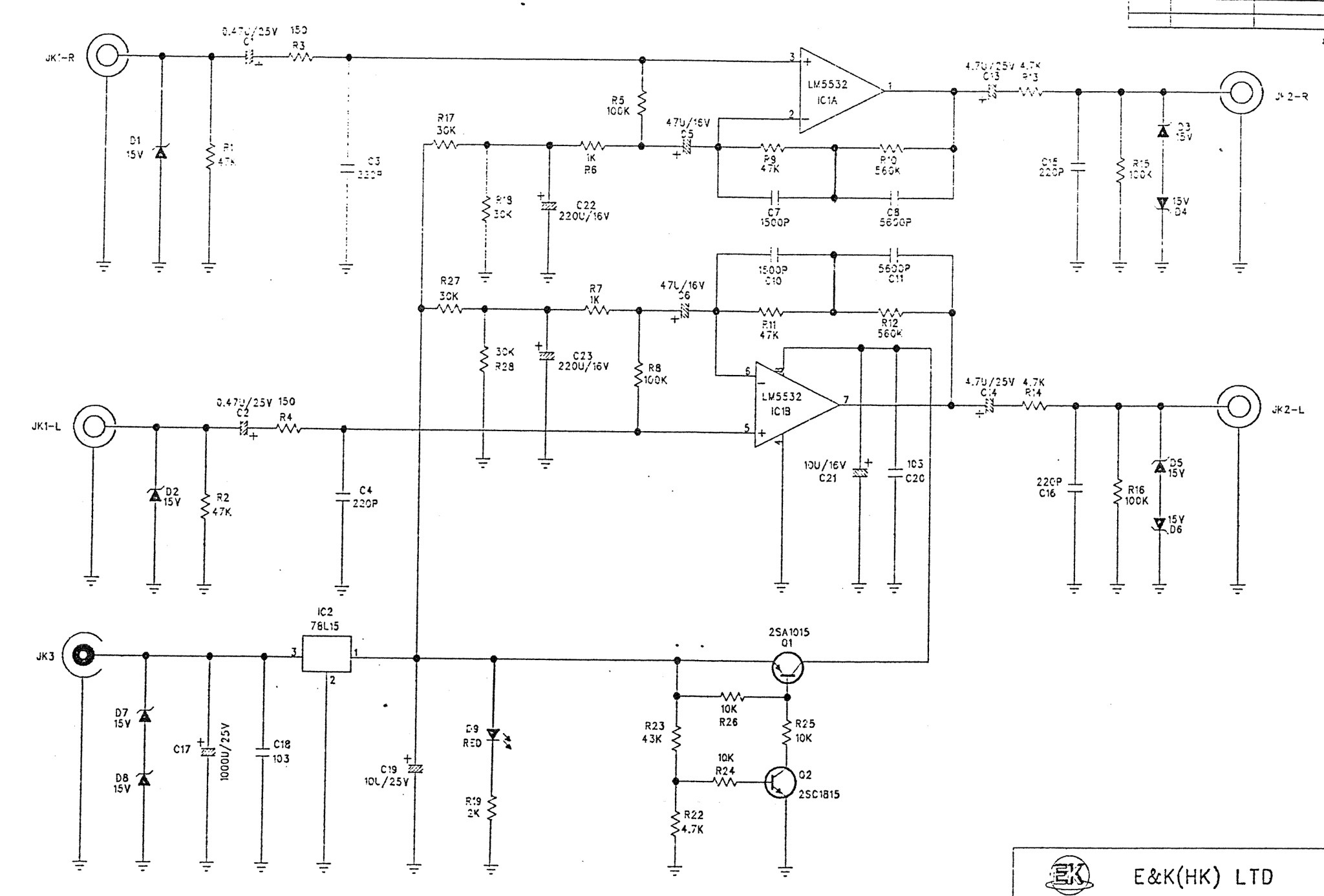
I'm a bit stumped and would love to know if anyone knows if what I'm attempting to do is even possible.

Thanks!

\$\endgroup\$
7
  • \$\begingroup\$ Any EE lesson is of course welcome. I'd love to learn more about how (and why) this works as it does, if that's not asking too much! \$\endgroup\$
    – Manuel
    Commented Dec 20, 2016 at 12:30
  • \$\begingroup\$ I would have looked at R6/R7 but at 1k0 its already low so at best you might only get another 3dB \$\endgroup\$ Commented Dec 20, 2016 at 12:35
  • \$\begingroup\$ What do you mean 'the output is low'? \$\endgroup\$ Commented Dec 20, 2016 at 12:43
  • \$\begingroup\$ There's nothing wrong with per say, it's just quite a bit lower than the rest of the line level input which leads to possible jump scares and possibly angry neighbors when I forget and switch sources. \$\endgroup\$
    – Manuel
    Commented Dec 20, 2016 at 12:44
  • 2
    \$\begingroup\$ I initially thought R28/R18 were responsible for the gain but that doesn't seem to be the case. No those are for biasing, roughly the gain is (R9+R10) / R6. But if you change any of those values then the EQ curve will also change. You would be better off adding an amplifier (without EQ) behind this circuit. \$\endgroup\$ Commented Dec 20, 2016 at 12:49

1 Answer 1

2
\$\begingroup\$

It looks like the answer was indeed R6/R7. These two resistors with the equalization network of R9 - R12 & C7 - C11 do indeed determine the gain.

As suggested, I simulated the circuit, and the default gain at 1kHz was 35db. Halving R6/R7 have raised the gain to 43db. Instead I chose a 1.3kOhm resistor in parallel via switch, giving about 600 Ohm and yielding an output of ~40db.

I also checked the RIAA equalization in the simulation for all three scenarios, and it's true that the equalization is slightly affected, the low-frequencies which are slightly more attenuated (less amplified) if the gain is increased. For 390 Ohms the deviation at the 20Hz end is about -3db. The equalization of frequencies from 1kHz and up isn't affected for some reason.

I picked 600 Ohm as final value since the deviation at 20Hz is about -1db VS the ideal RIAA-equalization curve and this is probably inaudible, especially since my speakers top out at around 40Hz anyway.

Upon implementing the above discussed changes (with a toggle switch) it seemed to bear the simulation results out.

\$\endgroup\$
1
  • \$\begingroup\$ It's good practice to accept your own answer so future users can easily recognise this question has been correctly answered. \$\endgroup\$ Commented Apr 11, 2017 at 12:53

Your Answer

By clicking “Post Your Answer”, you agree to our terms of service and acknowledge you have read our privacy policy.

Not the answer you're looking for? Browse other questions tagged or ask your own question.