5
\$\begingroup\$

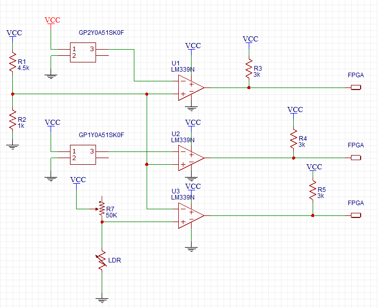
I am doing a project where I am using a FPGA board which connects to a circuit I designed. It has a quad Comparator (LM339N), a few resistors and an LDR; two distance sensors (GP2Y0A51SK0F) are connected to it by wires, and the circuit gets it's voltage from the FPGA board (DE0-Nano, 4.80V). The comparators are also powered by the 4.80V from the board.

This is the schematic: enter image description here

As you can see, the output of each distance sensor (this sensor only has 3 pins, I couldn't make the fourth hidden) goes to a comparator. The point was to turn the distance sensor into a proximity sensor and output '0' when it sees something at a certain distance. The FPGA then receives that '0' and acts. Somewhat the same with the LDR.

I can confirm everything worked when I used two different voltages supply when I tested this - one being 5V that goes into the distance sensor and one 3.3V that goes to the comparators. Both 3.3V and 5V came from a DC power supply.

Now, I'm using the DE0-Nano to supply power, the only source being one pin of 4.8V and one pin of GND. As you can see from the schematic, everything has one single power supply.

My problem - things are not working with the distance sensors; Trying to measure voltage at the output of each of the sensors I just get 0V, so obviously the comparators output nothing as well. I'm using a multimeter to try and check what the problem is, and when I tried to check for shorts (with a mode called continuity, I think), one of the following may happen (or together):

  1. A short between VCC and GND - but there is no physical connection between them, I check that with resistance mode.
  2. A short between the VCC and GND pins of the LM339N

1 and 2 will never happen at the same time.

  1. A short between one of the outputs of the comparators (U1 or U2) and VCC. When this happens, The 3K pull-up resistors are also a short.

Like I said, there is no physical connection between VCC and GND so I assume that the short the multimeter is seeing is due to pins having the same potential? Is it possible that the pull-up resistors are too small and that is why this problem happens? Is it possible that I fried the distance sensors?

Thank you for your help, I have been testing this for days and trying to figure out what the problem is.

Edit - here are a few screen shots from scope:

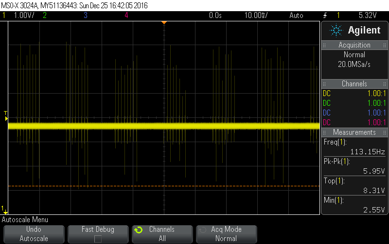
  1. This is the power pin: enter image description here

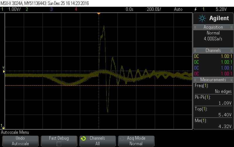
  2. This is the power pin, zoomed: enter image description here

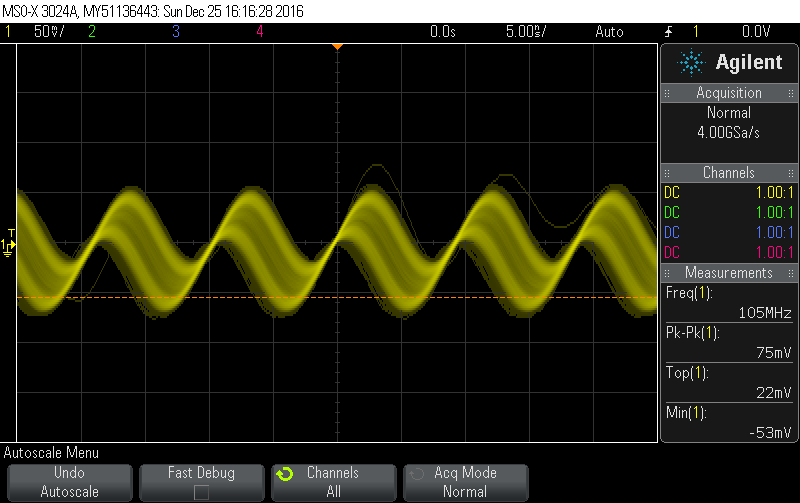
  3. This is the sensor's output: enter image description here

The output stays like this no matter what, so it doesn't really seem like it is working. maybe the amplitude is increasing but I don't think it matters (it could also be the other sensor and I don't remember).

Those screen shots are from one sensor only - the other shows different results, but when checking their output, none seems to actually respond.

\$\endgroup\$
3
  • 1
    \$\begingroup\$ Not sure what the overall plan here is, but you could likely swap out all the analog electronics with an embedded processor with multiplexed/multiple ADC inputs. Then simply program the processor for thresholds and possibly embellish the distance sensor with new features like hysteresis & noise reduction. FWIW, the Sharp detectors are really not analog. If you monitor the output closely you will notice a stair-step effect as the object moves closer-to / further-away-from the detector. \$\endgroup\$
    – st2000
    Commented Dec 24, 2016 at 15:31
  • 2
    \$\begingroup\$ Have experienced high pulse current with some of these kind of sensors. A rather large supply bypass capacitor close to these sensors may help. Some Vcc-to-ground capacitance should be added in any case. (Spec sheet only give average current 15mA) \$\endgroup\$
    – glen_geek
    Commented Dec 24, 2016 at 15:43
  • 1
    \$\begingroup\$ The continuity test function on multimeters does not indicate a short circuit (very near zero ohms) between its probes. Instead it indicates a "lowish" resistance - perhaps up to 100 ohms - between the probes. You should look at the actual resistance reading when doing this sort of test. \$\endgroup\$ Commented Dec 24, 2016 at 17:04

1 Answer 1

20
\$\begingroup\$

You have fallen into a classic XY problem1 trap. However, thanks for briefly mentioning the original issue, as that makes the overall situation easier to understand.

You have a genuine problem ("X"):

things are not working with the distance sensors.

That is not enough detail to help you with the actual problem, but I'll come back to that. You are having problems interpreting the results from an (unfortunately inappropriate) multimeter test, and that is what you were asking about ("Y").

However "Y" is the wrong issue on which to be spending your time, because getting an answer to that, won't help you with solving the original problem "X". As confirmation, below is the answer to your question "Y" (about the apparent shorts you measured) but it doesn't help resolve the real problem "X" (about the sensors, when powered by the DE0-Nano):

I'm using a multimeter to try and check what the problem is, and when I tried to check for shorts (with a mode called continuity, I think), one of the following may happen [...]

Using a typical multimeter in that way on a board with ICs, will usually lead to lots of false positive apparent shorts displayed on the meter. This is due to the ESD protection diodes (and other ESD protection structures) inside most ICs, which can conduct during that "continuity" testing.

So stop doing down this rabbit hole and back-up a few steps :-) Here is what I suggest:


1 There are several slightly different definitions of the XY problem so I linked to a Google search above, for readers who want to learn more. The terminology I use is:

"X [is] the underlying problem and Y the exposed question or request"

which is adapted from here.

\$\endgroup\$
9
  • 2
    \$\begingroup\$ You're right about not providing enough information - writing this question and drawing the schematic took a long time! :) I have edited the question, stating that the output of the sensor give me 0V, whether there is an object near them or not. Also, is there any other information I can provide? \$\endgroup\$
    – nettek
    Commented Dec 24, 2016 at 15:56
  • 2
    \$\begingroup\$ About the capacitors - should they be between VCC and GND? Can they be soldered into the board I designed (about 15-16 cm from the sensors?) \$\endgroup\$
    – nettek
    Commented Dec 24, 2016 at 16:00
  • 2
    \$\begingroup\$ @Eran - Understood & thanks for the schematic. It has confirmed there are no decoupling capacitors, so it has already been useful. While you updated the question, I was also updating my answer, and added an additional paragraph. IMHO you have several choices: (a) you could guess my hypothesis is correct, add (eg 47uF) cap at each sensor (not 15cm away) and retry; or (b) use an 'scope to view the waveform on the sensor power pins, in the "failing" configuration (powered by the DE0-Nano) and supply those 'scope screenshots; or (c) go back to the working config and retest, as in my answer. \$\endgroup\$
    – SamGibson
    Commented Dec 24, 2016 at 16:06
  • 2
    \$\begingroup\$ Yes I saw your edit, thanks for the additional info. I am already planning to retest this tomorrow with the previous configuration. I'll also do what you suggested with the scope and provide screenshots, and if really needed, add the capacitors. I just really hope I didn't fry the sensors or the comparators. \$\endgroup\$
    – nettek
    Commented Dec 24, 2016 at 16:15
  • 2
    \$\begingroup\$ @Eran - Great. As you said, I would also start with going back to the "working" config and retesting. If that works, move forwards from there. Comparing the sensor power waveform on the 'scope, between the working (external power supply) and failing (DE0-Nano power supply), will help confirm or deny my hypothesis. However even if my (lack of sensor power decoupling) hypothesis is wrong, I wanted to help by stopping you wasting your time on those continuity testing results. Then you can move forwards with investigating whatever your problem really is :-) Also, see new links in my answer. \$\endgroup\$
    – SamGibson
    Commented Dec 24, 2016 at 16:26

Your Answer

By clicking “Post Your Answer”, you agree to our terms of service and acknowledge you have read our privacy policy.

Not the answer you're looking for? Browse other questions tagged or ask your own question.