1
\$\begingroup\$

I am trying to determine the correct batteries required for my Arduino (Atmega 328) project. I have components which have both voltage and current ratings. I am adding up all the maximum current specifications from the components to determine the ideal mAH.

I am currently stuck on the Atmega328 chip. I read the datasheet, but I cant seem to find the specific current draw of the chip. My understanding is that the operating voltage is ~5V, and the current draw of the chip would be ~40mA. But if I am using 6 pins (3 analog, 3 digital), assuming they all output 40mA at the same time (which is unlikely as the 3 analog pins take in x,y,z values from an accelerometer), would it be safe to assume the current draw of the chip would be 240 mA? (this sounds wrong)

\$\endgroup\$
1
  • \$\begingroup\$ Build it, measure it, that's it. There are way too many variables to answer your question. \$\endgroup\$
    – Cano64
    Commented Dec 27, 2016 at 18:36

4 Answers 4

3
\$\begingroup\$

The datasheet of a microcontroller tells you the current it uses internally. Only you can determine how much additional current there might be going into the power pin or out the ground pin due to other pins sinking or sourcing current.

From what you say, the micro itself can take up to 40 mA. I don't know that particular micro, but that's certainly plausible.

The datasheet is also telling you the maximum that output pins are allowed to source. This is of no use in a power calculation. You use this information during the design to make sure this limit is not exceeded. The actual current that the external circuit draws from a output pin is dependent on the external circuit. Consider the limiting case where a pin is left unconnected. Clearly no current is going out that pin.

For example, let's say you're lighting a LED directly from a digital output. The processor runs on 5 V, and you have a green LED to ground with 300 Ω resistor in series. The current going out of the pin when high will be about 10 mA. The fact that the output could have sourced up to 25 mA, for example, is irrelevant.

\$\endgroup\$
1
\$\begingroup\$

Most CMOS microcontrollers, ATMEGA328 included, will consume more current from their DC supply when their clock runs at higher speed. On the ATmega328 data sheet, power consumption is spec'd at a speed of 1 MHz. When its clock is running, and the processor is processing, it will pull 0.2 mA current from a 1.8v DC power supply. This would be minimum current, will all input/output pins not supplying current.
When the clock is not running, current draw is reduced. Atmel specs "power-down" mode current draw as 0.1uA. With no clock, it cannot run programs. With its time-of-day clock running (32.768 kHz), current draw is 0.75 uA. This real-time-clock is separate from the processor clock.
Some processors brag about their speed-power performance, for example "100uA-per-MHz". This is a figure of merit, suggesting that a 100MHz. processor clock would require the processor to draw ten milliamps of DC supply current.

\$\endgroup\$
0
\$\begingroup\$

The atmega has a CPU, right? So if you make it work hard, you'll spend more energy. (It will get hot, albeit unnoticable) This is why your laptop CPU/GPU gets hot when you're playing computer games. Your doing a lot of calculations, the transistors are switching. Transistors lose energy when they switch on/off due to crossover. The datasheet will give you an idea what the CPU normally draws but you'll never know for certain.

About the pins, 40 mA is around the max rating a pin can provide. It's not what you are actually drawing. So, you can't use that math to calculate the current consumption.

And then there is the hardware problem. There are always current leaks in a hardware. You will never be able to calculate this most of the time. Only experiments will tell.

But the thing is, usually, for simple applications, only the pin currents matter. The others are usually less than that.

If you are researching this for a battery powered application, please consider sleep/deep sleep options.

Also, the best way to calculate current consumption (cheap and fast) is to get a resistor, calibrate it (find its real resistance), put it in series with atmega VCC and find the voltage drop. It works like a charm.

Oh and analog input pins don't draw much current. They draw just enough to sample the voltage but it's not that much. Only the GPIO pins in source/sink mode will draw/source that much current.

\$\endgroup\$
0
\$\begingroup\$

You will go blind trying to work out the average mA/h consumption of an Arduino by adding all the component and feature currents together.
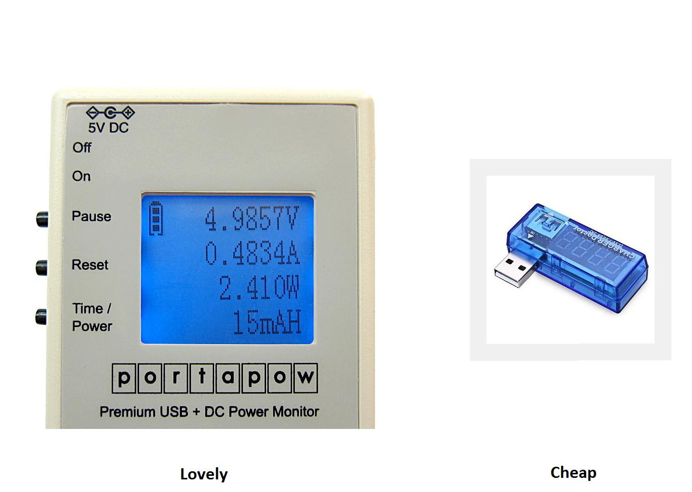
Buy yourself a USB voltage/current meter. This is placed in series with the USB line feeding the device and tells you the voltage and (average) current flowing. The USB current meters are available from ridiculously cheap on Ebay ($3) through quite expensive ($30+). My personal favorite is the Portapow which directly tells you the mA/h rating of the attached device. enter image description here

All the USB current monitors I have seen have the same problem when it get's to sleep states....they all have a limited minimum current resolution. When it comes to measuring sleep state current a series resistor can't be beaten.

\$\endgroup\$

Your Answer

By clicking “Post Your Answer”, you agree to our terms of service and acknowledge you have read our privacy policy.

Not the answer you're looking for? Browse other questions tagged or ask your own question.