1
\$\begingroup\$

Suppose I have a 12-0-12 1Amp step down transformer. The primary coil is connected to 220V AC. How is the current flow in primary coil impacted in following 3 scenarios:

  1. When no load connected to secondary
  2. When 250mA is drawn from secondary
  3. When 500mA is drawn from secondary.

If the primary coil's current flow remains unchanged regardless of the amount of current drawn from secondary, which form of energy does the primary coil's current gets converter on no secondary load condition?

And if the current flow in primary varies, which principle of physics basically drives the factor - how much current should flow in the primary coil, for a given amount of load on secondary coil?

\$\endgroup\$
6
  • 1
    \$\begingroup\$ What are your calculations? \$\endgroup\$
    – D.A.S.
    Commented Dec 28, 2016 at 22:38
  • \$\begingroup\$ Have you read en.m.wikipedia.org/wiki/Transformer? \$\endgroup\$
    – Tyler
    Commented Dec 28, 2016 at 23:01
  • \$\begingroup\$ @TonyStewart.EEsince'75 my calculation suggests no current should flow in primary when no load is attached to secondary. But in real time that doesn't happen. I am kind of curious why it is so. And I also want to know if the amount of current flow in primary drives how much current should flow in secondary, or just the opposite one- amount of current drawn from secondary actually drives the amount of current flow in primary. \$\endgroup\$
    – sribasu
    Commented Dec 29, 2016 at 6:02
  • 1
    \$\begingroup\$ A real transformer has an excitation current of typically 10% or rated current unrelated to load. 220 to 24V is almost 10:1 turns ratio ( 110:12) with a center tap. which steps down voltage and steps up current capacity for a given VA rating. Thus Primary current is almost 10% of output ( neglecting excitation current) \$\endgroup\$
    – D.A.S.
    Commented Dec 29, 2016 at 6:13
  • \$\begingroup\$ What primary (magnitizing) inductance do you have? What impedance does that equal at mains frequently? What voltage do you apply? Now solve your ohms law for the unknown current. \$\endgroup\$
    – winny
    Commented Dec 29, 2016 at 8:39

4 Answers 4

2
\$\begingroup\$

A transformer is basically two coils of wire (inductors) sharing a common core. If you don't connect a load to the secondary you might as well regard a transformer as an inductor. That inductor has (obviously) inductance and the current it takes is dependent on the applied voltage, frequency and inductance. So, usually, the number of turns on an AC power transformer are quite high and in the region of a thousand turns.

This means a few henries of inductance and possibly around 100 mA RMS current taken. This is just the primary with no secondary current being taken. This is typical of a transformer with a VA rating around 30 VA and will vary for different transformers in different applications i.e. it's just a rough guide to give a feel for the numbers involved.

This current is called the magnetization current and is the major source of transformer core saturation problems. It remains ever-present irrespective of what current you take from the secondary but, of course, it is added-to by the primary current caused when connecting a load to the secondary.

So, for a simple (and otherwise perfect) 1:1 transformer taking 0.1 A magnetization current and with a resistive load current of 1 A on the secondary, the total primary current comprises the 0.1 A magnetization current and the 1 A load current.

Given that the load current is resistive (as stated) and the magnetiztion current is due to the primary inductance, the two currents are 90 degrees out of phase hence the total primary current is \$\sqrt{1^2+0.1^2}\$ = 1.005 A.

For a 10:1 step-down transformer with 10 A on the secondary, it's exactly the same primary current.

Complicating things a bit; the magnetization current won't be particularly sinusoidal because iron/steel etc does not have a linear relationship between applied field (ampere turns) and flux density (teslas). That ratio is the permeability of the core material \$\mu\$. Also, the relationship has hysteresis and this gives rise to a resistive loss (called unsurprisingly hysteresis loss) so now there is an extra current present in the primary (irrespective of secondary load current seen by the primary).

Because the steel/iron core is a conductor it can act like a shorted turn therefore laminates are used that are insulated from each other thus, you only get small eddy currents in each laminate. These small currents flowing through the iron/steel generate heat and this is another loss that has nothing to do with load current. So, in summary the currents in the primary are: -

  • Magnetization (reactive and not a loss)
  • Hysteresis loss current (resistive)
  • Eddy current losses (resistive)
  • Load current

NB - hysteresis and eddy current loss is sometimes grouped under the term "iron loss".

But there's also leakage inductance and winding resistance to consider. Any current flowing in the secondary or primary flows through copper but it still has resistance and there will be a small volt drop and \$I^2R\$ power (copper) loss. Also, all the turns in the primary do not 100% magnetically couple to all the turns in the secondary so, in effect, there are leakage inductances which (like copper loss) reduce the output voltage on the secondary under load conditions.

It all boils down to the equivalent circuit of a transformer: -
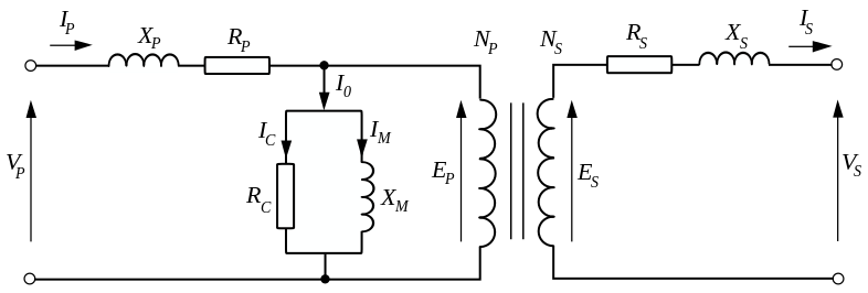
enter image description here

\$X_P\$ and \$X_S\$ are the leakage inductances i.e. those turns that don't couple. \$R_P\$ and \$R_S\$ are the copper losses of primary and secondary. \$R_C\$ represents the core loss (eddy current and hysteresis losses) and \$X_M\$ is the magnetization inductance.

What remains is a perfect lossless transformer represented by the transformer symbol in the picture; it has perfect characteristics and transfers power 100% efficiently - all the components hung aroud it turn that perfect transformer into the everyday imperfect transformer we use.

\$\endgroup\$
1
  • \$\begingroup\$ This answer is just incredibly good! \$\endgroup\$ Commented Dec 29, 2016 at 13:24
1
\$\begingroup\$

When no load is connected to the secondary the magnetizing inductance is directly across the line (along with some leakage inductance).

With no connection to the secondary you have just the primary windings around a core which form an inductor. If everything were ideal the current in the primary would be 100% reactive and given by Vin/Xl.

There will be some ESR associated with the primary windings as well as proximity and AC losses. So the current will be proportional to the total impedance across the line, with reactive and real components. If it's a "good" transformer the current will still be mostly reactive.

When you start to draw current from the secondary, the primary current will increase based on the turns ratio. Np/Ns = Is/Ip, neglecting some of the load dependent losses.

Wikipedia has a decent explanation as well as the standard equivalent circuit that you can use to be more accurate than the above:

Wikipedia Article On Transformers

\$\endgroup\$
0
\$\begingroup\$

The pyhsics principle that allows energy to cross the transformer is magnetic transfer (mutual inductance). The AC current in the primary is creating a magnetic field, that is mostly (but not entirely) contained within the core of the transformer. The magnetic field in the core of the transformer induces a proportional current in the secondary.

An imaginary "perfect" transformer would draw zero current from the primary if the secondary were disconnected, but transformers in this universe have losses. You can experience this by attaching your transformer with no load to a power source, walking away for an hour, coming back and noticing that it is warm.

\$\endgroup\$
2
  • \$\begingroup\$ Exactly, I noticed the heat. Is there any explanation what how the secondary coil's current draw drives the current draw in primary? Transformer's principle says, current flow in primary causes induction of current in secondary. I really didn't find a suitable explanation on how secondary coil's current thirst actually drives the amount of current flow in secondary. \$\endgroup\$
    – sribasu
    Commented Dec 29, 2016 at 6:00
  • \$\begingroup\$ "The magnetic field in the core of the transformer induces a proportional current in the secondary" - no it does not - it produces a voltage in the secondary. When the secondary is loaded, that voltage (and the load) produce a current. \$\endgroup\$
    – Andy aka
    Commented Dec 29, 2016 at 11:49
0
\$\begingroup\$

The current in the primary causes a magnetic field, the magnetic field causes a voltage which inhibits current in the primary. This is called "magnetising current"

The maenetic field also causes voltage in the secondary.

When current is allowed to flow in the secondary it cancels some of the magnetic field, this reduces the voltage that's inhibiting current in the primary, this allows more current to flow in the primary also.

\$\endgroup\$

Your Answer

By clicking “Post Your Answer”, you agree to our terms of service and acknowledge you have read our privacy policy.

Not the answer you're looking for? Browse other questions tagged or ask your own question.