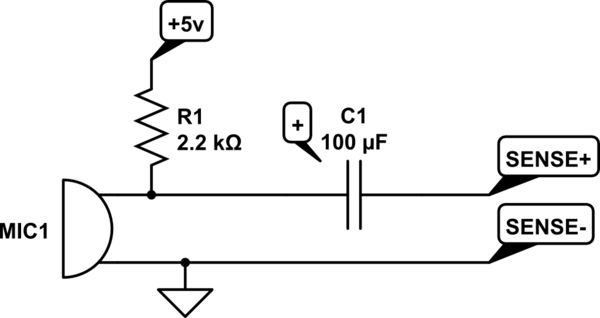
I've been trying to set up a microphone circuit for use in an AVR, essentially just to detect levels of noise. I observed some strange behavior in the amplified circuit I set up, so i elected to strip the circuit down to its base functional unit to see if I could figure out what the problem was. Schematic follows.

simulate this circuit – Schematic created using CircuitLab
The resources that I've used to build this circuit all seem to indicate that the type of cap used doesn't matter, so I opted for the higher-capacitance electrolytic. This did not behave as expected.
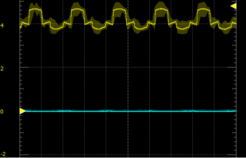
The following is a waveform captured from the circuit using an electrolytic cap.
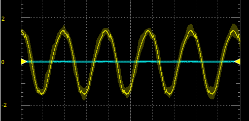
Now, the ceramic cap:
To be clear, these waveforms are captured while the room is quiet. blowing into the microphone produces a response.
The ceramic capacitors I have do not dampen the 60Hz noise to my liking, and it seems silly to wire a bunch of them in parallel when I have a few much larger electrolytic caps.
I've tried a few different sizes of electrolytic caps, with the same result.
I've tried reversing the polarity, with the same result.
Why am I seeing this discrepancy? How can I remedy the situation?
Additionally and secondarily, is there an established best practice for using a microphone with AVR?
EDIT turns out i'm seeing this effect because my cheap chinese power supply has a poor rectifier :^)


