0
\$\begingroup\$

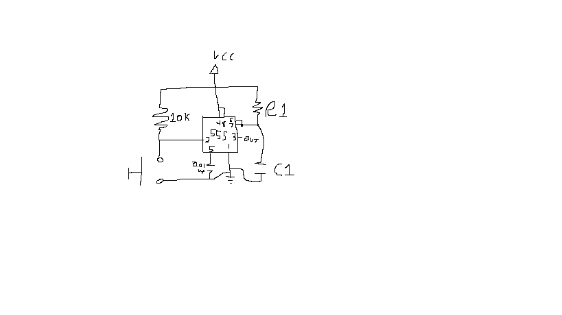
As I understand, resistors limit current. I also think that resistors allow all voltage to pass through them, but now I am confused. Apparently, the 555 timer in mono stable mode has its output high once the trigger goes low until the voltage on its threshold is 2/3 of the voltage in vcc (stabilized by control). What I don't understand is why the 555 timer only is looking at the voltage given off by C1, and why the voltage coming through R1 from VCC doesn't trigger the threshold itself.

Why is the threshold not activated by the voltage coming through R1? Is the capacitor a 'short circuit,' so it bypasses the threshold?

--edit-- Why does the voltage between VCC and ground not trigger the threshold?

Circuit

\$\endgroup\$
1

3 Answers 3

2
\$\begingroup\$

Voltage does not "pass through" resistors, or anything. Nor is it "given off" by capacitors.

Voltage, more rigorously called "electric potential difference", is a difference between two things. When the voltage of only one thing is given, it's implicitly assumed the reference point is an arbitrarily selected node in the circuit we call "ground".

Height is another kind of potential in a gravitational system. Let's say I measure the difference of height between two points on Earth, and I call this the "feetage". The feetage of Mt. Everest is about 29,000 feet, relative to sea level. Does that feetage "pass through" the mountain? Or is it "given off" by the mountain? No, that doesn't make any sense.

Pressure is another kind of potential. For pressure we can define a vacuum as zero pressure, so we can talk about absolute pressure. We can also talk about the difference in pressure between two things. For example the difference in pressure between the air in your lungs and the air around you is usually very small, because when it isn't air moves in or out of your lungs via your nose until the pressures are equal. Does the pressure "pass through" your lungs? No, it's the air that passes through.

The "air" in an electrical system is called electric charge, measured in coulombs. The rate at which electric charge is moving is called current, measured in amperes.

If the passage of air is restricted, then the pressure difference will be greater, and less air will flow. If the passage is nearly unrestricted, then the difference in pressure will be very little, and much air will flow. This is resistance, and it works similarly in pneumatic, hydraulic, and electric systems. Resistance doesn't really regulate current: it just determines at what rate fluid (air, hydraulic fluid, electric charge, etc) will flow for a given difference in pressure or electric potential (voltage) between two things. This relationship between voltage, current, and resistance is given by Ohm's law.

What the 555 timer is looking at is the difference in electric potential between the bottom of C1, and the top. The voltage across the capacitor is the integral of the charge that's passed through it: passing one way the charge increases the voltage, and passing the other way decreases the voltage. And in turn the charge passing through C1 is a function of the battery which is pumping charge through R1 in one direction, and the 555 which is letting charge flow out in the other direction (or not, depending on which state it's in).

Hopefully that makes things more clear.

\$\endgroup\$
1
\$\begingroup\$

resistors limit current

That statement is too general, resistors can be said to resist current. In some applications resistors can be used to limit current - a typical example is in series with an LED and a constant-voltage power supply.

resistors allow all voltage to pass through them

That is only true under specific circumstances, namely when the current is zero (or too close to zero to measure the effect on voltage)

The voltage across a resistor V is given by V = IR where I is current and R is resistance. For some narrow ranges of voltage, current and temperature, this resistance can be assumed to be nearly constant for resistors.

I don't understand is why the 555 timer only is looking at the voltage given off by C1, and why the voltage coming through R1 from VCC doesn't trigger the threshold itself.

Before the power supply is first connected, the capacitor is "uncharged", there is no voltage difference between the two sides of the capacity. this means that pins 6&7 are at 0 volts (relative to ground & pin 1)

When the power supply is connected, current flows through the resistor R1, "charging" the capacitor. As the charge grows, the voltage across the capacitor rises, so the voltage at pins 6&7 rises.

The operation of this "one-shot" circuit is explained here


Voltage, Charge, Current, Connected, Motion, etc

Voltage doesn't really "come through" resistors. Or at least, I believe that's not a useful way to think about this sort of electronics.

Voltage isn't moving. The only things moving around are charge-carriers (e.g. electrons and holes). We call the movement of charge carriers current and measure it in units called Amps.

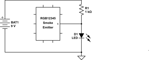
Consider this circuit

schematic

simulate this circuit – Schematic created using CircuitLab

Even though there is a conducting path from pin 6 to Vcc, Pin 6 does not see Vcc, it sees the voltage at the junction between pin 6, the LED and the resistor. This voltage is held by the LED at close to whatever it's nominal forward voltage is, perhaps 2V say. This is almost regardless of the exact value of Vcc within some reasonable range.

\$\endgroup\$
9
  • \$\begingroup\$ Why does the voltage charging the capacitor not trigger the threshold? \$\endgroup\$
    – pepperjack
    Commented Jan 20, 2017 at 16:52
  • \$\begingroup\$ @Evan_K2014. Voltage doesn't charge the capacitor, the movement of charge (i.e. current) does. The voltage is a kind of measurement of a "force" that is exerted on the charge carriers. This may seem like nit-picking but it's important if you want to understand what is happening. The capacitor is discharged through pin 7, this makes the voltage drop, when the voltage at pin 6 drops below a certain voltage known as the threshold voltage, the output at pin 3 is changed by the 555. \$\endgroup\$ Commented Jan 20, 2017 at 17:02
  • \$\begingroup\$ What I'm trying to understand is why the voltage given off by the source does not trigger the threshold, and why only the capacitor's does. \$\endgroup\$
    – pepperjack
    Commented Jan 20, 2017 at 17:06
  • \$\begingroup\$ @Evan_K2014 Pin 6 is not connected to the source (Vcc), it is connected between R1 and C1. The "source" (Vcc) is at a voltage (relative to ground) but does not "give off" voltage. \$\endgroup\$ Commented Jan 20, 2017 at 17:07
  • \$\begingroup\$ Ok, my wording was incorrect. Voltage between Vcc and Ground charges C1 through R1. As C1 charges, voltage increases between it and ground. Why does the voltage between Vcc and ground not trigger the threshold? Why does only the voltage between C1->threshold->ground trigger the threshold? Is R1 'preventing' more than 2/3 of the voltage from going through? \$\endgroup\$
    – pepperjack
    Commented Jan 20, 2017 at 17:11
1
\$\begingroup\$

What I don't understand is why the 555 timer only is looking at the voltage given off by C1,

because that's the way the circuit is connected - the timer only cares about the voltage on pin 6 to determine its discharge (on pin 7). if you had connected something else to pin 6, the timer will watch the voltage across that to determine if a discharge should happen or not.

and why the voltage coming through R1 from VCC doesn't trigger the threshold itself.

it does. to prove that, if you disconnect R1 from C1, the circuit behavior will change, :)

\$\endgroup\$

Your Answer

By clicking “Post Your Answer”, you agree to our terms of service and acknowledge you have read our privacy policy.

Not the answer you're looking for? Browse other questions tagged or ask your own question.