12
\$\begingroup\$

Is it possible to use a PCB pad as a button? I think of using it to switch on a curcuit that is only supposed to be enabled, when the user holds it in its hands.

As inspiration, I used the pads that are being used on soft touch buttons on keyboards or in calculators:

enter image description here

I know that the human body has a quite high resistance, so what would be an appropriate circuit to detect the touch input? Bare hardware only. I don't want to use any microcontroller here.

\$\endgroup\$
4
  • 6
    \$\begingroup\$ You mean a capacitive touch sensor? \$\endgroup\$
    – PlasmaHH
    Commented Jan 23, 2017 at 10:25
  • \$\begingroup\$ @PlasmaHH This might be another possibility, but I though of something like amplifying the current that flows when bridging the above pad with your finger, unsing it to operate a mosfet or something \$\endgroup\$
    – mxcd
    Commented Jan 23, 2017 at 10:38
  • 2
    \$\begingroup\$ Depending on the power requirements of your design, capacitive sensing might be too power hungry. You can get away with the 50Hz (probably). If you touch the gate of a mos, you turn the mos on. Also, you usually break it, so it must be somehow protected, but it is a good starting point. \$\endgroup\$ Commented Jan 23, 2017 at 10:40
  • \$\begingroup\$ No... He's talking about resistive sensing. \$\endgroup\$ Commented Jul 29 at 15:30

2 Answers 2

14
\$\begingroup\$

For reliability reasons I wouldn't go for an open-gate design and rely on the 50Hz noise. It probably might work, but your idea of using interleaved fingers should work quite well.

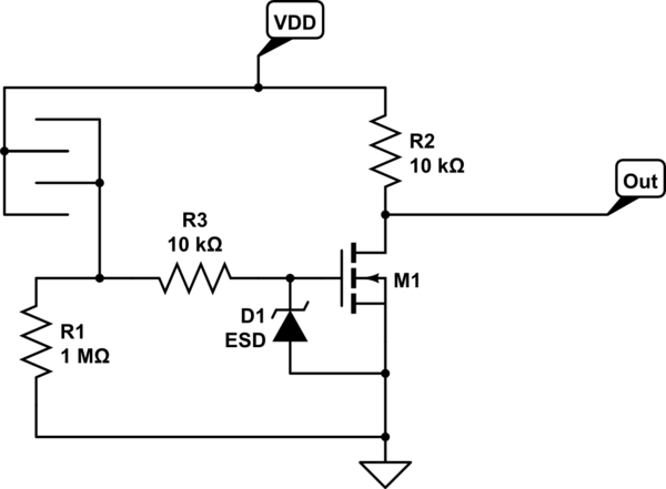
The resistance of dry skin is somewhere between 1k and 100k, so you could think of an NMOS transistor (find one with ESD protection) and a large pull down of e.g. 1M ohm. Then you can use the finger as a pull-up resistor to turn on the mosfet.

schematic

simulate this circuit – Schematic created using CircuitLab

You could also use a bipolar (or darlington) transistor, they are less vulnerable to ESD defects, but cannot supply a large current at the output if needed so you would need to buffer the output.

A capacitive sensor would be an alternative solution, but requires a more complicated circuit.

\$\endgroup\$
2
  • 4
    \$\begingroup\$ I would consider adding a 10k resistor between the cathode of D1 and the junction between R1 and the right-hand side of the sensor to limit the instantaneous current into the gate of M1 from a static discharge and help D1 do its work by generally slowing fast edges down. If you find this circuit particularly noise-prone, a 100pF or so capacitor across R1 may help that - you'll have to build it and try it out! \$\endgroup\$
    – stefandz
    Commented Jan 23, 2017 at 12:13
  • 1
    \$\begingroup\$ Good point, I'll add it to the circuit diagram \$\endgroup\$
    – Douwe66
    Commented Jan 23, 2017 at 12:14
14
\$\begingroup\$

It is possible to use resistive connection pads like you show, but capacitive pads are generally better. Resistive pads leave a direct connection to the circuit open to the outside. They are therefore susceptible to damage from static discharge and noise.

Capacitive pads are a better method, although they require a bit more firmware to sense, at least if you want to do it well. Note that to get even rudimentary noise immunity, resistive pads require firmware too. Just connecting two pads to something sensitive, like the gate of a FET, is a bad idea. You won't be able to cancel common mode and other ambient noise.

Here is the layout of a small board I did recently just to research capacitive buttons:
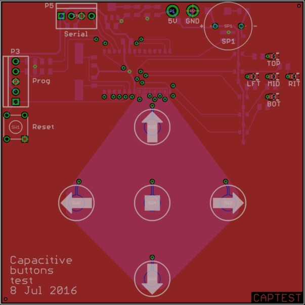
The cap pads are small disks 150 mils (3.8 mm) in diameter and otherwise surrounded by ground on the top layer. The microcontroller is a PIC 16LF1786. It and all the other parts that aren't for directly interfacing with the user are mounted on the bottom of this two-layer board.

The PIC continually scans the pads. When it detects a change in the pressed/released sense of a pad, it sends a message over the serial port, updates the lights at top right, and emits a beep on a press.

For testing, I can have the PIC regularly send its internal values for the pressedness of each pad. Here is a plot of all five raw sense values, in addition to the overall something-is-pressed digital state as I pressed each pad in succession with my finger:
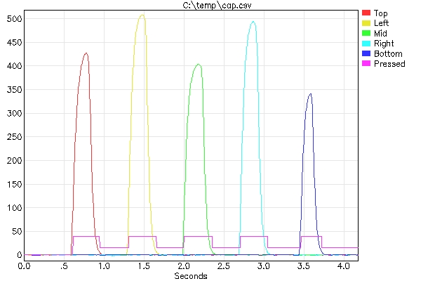
As you can see, the noise immunity is exceptional. Even the weakest signal was well over 300, while noise was ±2 or so.

The magenta trace labeled "Pressed" shows the OR of the individual button pressed states. Its levels show the press and release thresholds. There is much extra signal that is not used in this case. These particular thresholds were tweaked to be able to tolerate a few layers of paper above the buttons.

Of course there is some clever handling of the button lines and processing, even if I say so myself, but clearly the results are achievable with quite a modest microcontroller.

I am using this in a real product where the same micro is also managing a character display. That's a basic user interface subsystem I plan to re-use in several future products. It interfaces to the main system controller over a serial port. The main controller sends commands for writing to the display, and receives asynchronous messages whenever the state of a button changes.

\$\endgroup\$
4
  • \$\begingroup\$ What are the units of the Y axis in your plot? Are pads simply connected to the pins, or are there other components involved? \$\endgroup\$ Commented Jan 23, 2017 at 15:07
  • 1
    \$\begingroup\$ @Dmitry: The Y axis shows the internal "how much the button is being touched" measure. It is derived from raw A/D values, but there are multiple A/D readings envolved, and there is significant processing on those readings. There was no attempt to keep them in particular units, since these values are relative to each other and arbitrarily entered thresholds. Very roughly they are in units of about 800 uV differential between reading. 350 means about 280 mV, but again, it's not really that simple. \$\endgroup\$ Commented Jan 23, 2017 at 15:34
  • \$\begingroup\$ So you're driving the pads high and low, and measure some sort of charge/discharge rate using ADC? \$\endgroup\$ Commented Jan 23, 2017 at 15:42
  • 1
    \$\begingroup\$ @Dmitry: I'm driving the something else high and low, then measuring the step change in the pads. Nothing is time-based other then allowing enough settling time to take readings. \$\endgroup\$ Commented Jan 23, 2017 at 16:00

Your Answer

By clicking “Post Your Answer”, you agree to our terms of service and acknowledge you have read our privacy policy.

Not the answer you're looking for? Browse other questions tagged or ask your own question.