13
\$\begingroup\$

Although I've been working with op-amps for a while, the following question never occurred to me before today.

enter image description here

Consider first the op amp on the left (A). The negative terminal is connected to ground, and a small voltage \$V_d\$ is applied between the positive terminal and ground. If the output voltage is measured with respect to ground, it should read \$A \cdot V_d\$.

Now consider the op-amp on the right (B). This time, \$V_d\$ is applied directly between the negative and the positive terminals, with no reference to ground. If the output voltage is measured with respect to ground, would it still read \$A \cdot V_d\$? How could this be, since this op-amp has no idea where ground is?

\$\endgroup\$
6
  • 2
    \$\begingroup\$ if I remember it's the difference across the voltage terminals that determine the output. \$\endgroup\$ Commented Jan 27, 2017 at 21:14
  • 1
    \$\begingroup\$ Forget voltage think current \$\endgroup\$ Commented Jan 27, 2017 at 21:27
  • 6
    \$\begingroup\$ The OA has no idea where ground is and if left floating, it will drift out of range. You must define the common mode or reference voltage and the differential voltage. All OA's have a limited CM input range and will not work as you showed it. (forgot to mention with a typical Av of 10^6 and noise levels in uV, that wont work without negative feedback either._ \$\endgroup\$
    – D.A.S.
    Commented Jan 27, 2017 at 21:46
  • 2
    \$\begingroup\$ The practical effect of this circuit is that the outputs will likely be Vcc when Vd is positive and -Vee when Vd is negative. \$\endgroup\$
    – Daniel
    Commented Jan 27, 2017 at 22:42
  • 3
    \$\begingroup\$ A tiny creature comes out a window in the Op Amp and if he sees ground, there's a ground. If he sees snow, he goes back in and hibernates. It works great on Ground Hog Day especially. This is not mentioned in most literature because most engineers don't believe in it, but it is true. And now you know. \$\endgroup\$ Commented Jan 31, 2017 at 19:05

9 Answers 9

19
\$\begingroup\$

How does anything know where ground is? Ground is just a symbol we stick on the schematic to make it easier to read. None of the components in a normal circuit read the schematic, so none of them know where ground is.

In the case of op-amp B, the output voltage will be either the maximum voltage the op-amp can output (limited by the supply rails), or the minimum, depending on the polarity of the voltage source on the input.

And building such a circuit in practice, you'd have a problem: there's no path from the voltage source on the input to anything else. As such, the actual values there will be defined by the input bias current of the op-amp and other non-ideal behaviors, so what you'll get is something strange that's mostly a function of the details of that particular op-amp.

You'll probably find it easier to think of op-amps not as amplifying the difference between their terminals. In practice, op-amps are usually operated with negative feedback: when they aren't, they tend to be called comparators. So, the op-amp tries to adjust the output voltage such that the two inputs are equal, and for the ideal op-amp with infinite gain, this is exactly the case: the inputs will always be at the same potential.

\$\endgroup\$
7
  • \$\begingroup\$ So what would the multimeter read on op-amp (B) between v_o and ground? \$\endgroup\$
    – MGA
    Commented Jan 27, 2017 at 21:19
  • \$\begingroup\$ @MGA added the answer in edit \$\endgroup\$
    – Phil Frost
    Commented Jan 27, 2017 at 21:23
  • \$\begingroup\$ The op amp would not be a comparator for small values of Vd. Suppose Vd for op amp B is less than (Vcc +Vee)/ Aol. Then you have Vo=(V+-V-)*Aol. What is Vo in relation to in this equation? Assume a perfect op amp. \$\endgroup\$
    – peteey
    Commented Jan 27, 2017 at 22:36
  • \$\begingroup\$ @petEEy The same could be said of any real comparator, since like all real devices, it has finite gain. It's still a comparator though. \$\endgroup\$
    – Phil Frost
    Commented Jan 28, 2017 at 1:43
  • \$\begingroup\$ That doesn't answer the question. What would you reference the value of Vo when Vd is smaller than the rail range divided by the open loop gain? Suppose the rails are +/- 20, Vd is 1uV, and Aol is 10^6. Vo would be 1V with respect to what? \$\endgroup\$
    – peteey
    Commented Jan 28, 2017 at 1:46
7
\$\begingroup\$

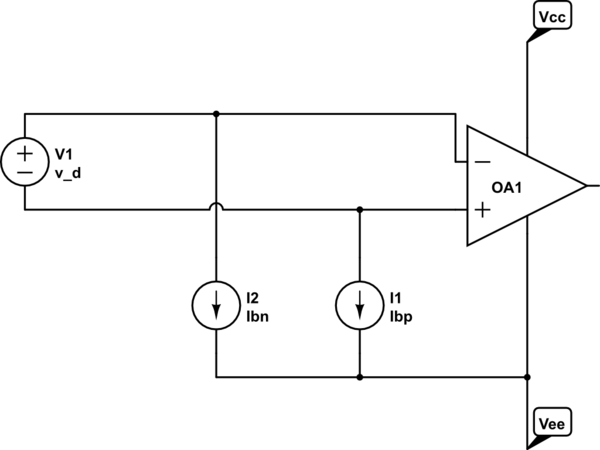
The input bias currents behave as below, where I1 and I2 are the respective input bias currents and I2-I1 is the input offset current.

schematic

simulate this circuit – Schematic created using CircuitLab

The op-amp will only operate properly if the inputs are within a given common mode range (with respect to Vcc and Vee). That might be very close to the supplies or it might be a volt or two away from either or both supply.

As you can see in your right-hand example, there is no path for I1+I2, so the inputs will rapidly approach the supply rail (at which point the current sources stop being more-or-less ideal).

It's possible that some op-amps under some conditions might happen to sort-of work but it's not something you should rely upon. Always provide a DC path for both inverting and non-inverting inputs. The above example provides a path for only the offset current (I2-I1). The total bias current (I1 + I2) has no path.

As to what exactly the output would be- you can think of it as Avv_d(Vcc+Vee)/2, though the offset voltage of the op-amp times the gain is usually enough to saturate the output at either rail, so the mid-rail adder (Vcc+Vee)/2 is sort of arbitrary. Hopefully that makes sense to you.

\$\endgroup\$
5
  • \$\begingroup\$ Hi Spehro Pefhany, I can't understand what "The above example provides a path for only the offset current (I2-I1)" means. IMO the offset current is not another current but the difference between the magnitudes of the two input currents. So no any current flows in the picture on the right. \$\endgroup\$ Commented Feb 8, 2023 at 8:16
  • \$\begingroup\$ @Circuitfantasist If one current was +1nA and the other -1nA (not impossible for a CMOS-input op-amp) 1nA current would flow through the voltage source. The net bias current is zero in this case. Since the bias currents vary with input voltage this is not totally outlandish. \$\endgroup\$ Commented Feb 8, 2023 at 9:34
  • \$\begingroup\$ Maybe I'm missing something. According to my understanding, current cannot flow through the floating input source because it would have to come out of one input, pass through the source, and enter the other input. But currents can be only incoming (NPN transistors) or only outgoing (PNP transistors). \$\endgroup\$ Commented Feb 8, 2023 at 11:20
  • 2
    \$\begingroup\$ @Circuitfantasist In the case of a CMOS-input op-amp the current will only be leakage and it could be of either polarity on each input. If you allow one input to float it will drift to some voltage between the rails. If you connect the two inputs together then they will, in general, float to a different voltage with some tiny current flowing between the inputs. The generality of PNP and NPN current directions applies within the CM input range, but.. \$\endgroup\$ Commented Feb 8, 2023 at 12:25
  • 1
    \$\begingroup\$ I agree and have thought so regarding FETs. But here I was guided by the view that the input bias currents are created by the current source in the emitters and the offset current represents the difference between them. Thanks! \$\endgroup\$ Commented Feb 8, 2023 at 13:18
5
\$\begingroup\$

First of all, ground is the arbitrarily chosen point where you reference all the voltages in the circuit. In the most common simple circuit configurations ground is chosen either as the negative terminal of the single supply source or the mid point of a symmetric supply, which is (as you noted) the way op-amps are intended to be powered (at least when dealing with "standard" circuits often found in basic literature).

So you're puzzled because the usual op-amp model has a differential input but it's output is referenced to ground, hence the question: how does the op-amp know where ground is? It simply doesn't know, it guesses.

What do I mean? The internal circuitry of the op-amp is built so that, ideally, with zero differential input the output would sit at a point halfway between the op-amp's supplies.

If the supplies are symmetric (say ±15V) that point just happens to be ground (0V), but only if you chose ground as the midpoint between supplies (most common scenario).

On the other side, if you power the op-amp with a single power supply, say 15V, the output will sit at 7.5V.

Of course this is an ideal behavior, since bias currents, offset voltage and common mode range will have an influence on the real device.

See also this excerpt from Op Amps Applications Handbook, by Walt Jung, from Analog Devices, chapter 1, p.5 (yellow emphasis mine):

enter image description here

\$\endgroup\$
3
\$\begingroup\$

An op-amp has no idea where ground is.

Op-amps are differential amplifiers. They amplify the difference between the two inputs and (ideally) ignore any common-mode voltage. There's no difference between the two circuits in your diagram. Neither op-amp's output is referenced to ground. The output bias point is probably close to mid-way between the two supplies. You could measure try to measure it by shorting the inputs together, but you'll have to deal with the input bias voltage and current too. It's probably not worth the trouble.

Fortunately, you don't have to worry about the output bias point or the "real" reference voltage, because they don't matter for either of an op-amp's common uses. If you're using the op-amp as a comparator, you want the output to be either as positive as possible or as negative as possible, even for a tiny differential voltage. If you're using the op-amp in a linear circuit, you use negative feedback, which which causes the output to be referenced to the positive input.

Real physical op-amps aren't perfect differential amplifiers, so in real life common-mode voltage has a small effect on the output. As Phil's answer says, the construction of the op-amp matters too. But I don't think that's important for what you're asking about. Op-amps aren't built to do what your circuit is trying to make them do.

\$\endgroup\$
3
\$\begingroup\$

See the following elementary drawing of the internals of the opamp:

opamp principle

The input transistors need their base current - both of them! The current is usually less than 1uA. The opamp determines himself how much he takes, but it must be available and for both input it must be directed to inside the transistor. If you connect "something" only between the + and - inputs, then the currents can't be simultaneously towards the transistors because that "something" should create new electric charge. It's Kirchoff's law.

In practical opamp circuits the way for the input base current (=bias current )is some conductive part between the input and the supply voltage rail or the GND. In this case (see the arrows in the input transistor emitters) the -VE supply rail is impossible as the right direction input current supplier, but +VE rail is ok and also GND if its lifted above the -VE potential by either adding a battery betveen -VE and GND or by a resitor that is connected to +VE.

Fet inputs are not better. Without a galvanic connection to elsewhere than the "something" between the inputs, they soon drift to undetermined state due the accumulated leakage charge into the gates of the fets.

\$\endgroup\$
1
\$\begingroup\$

This becomes clearer with some information on the internals (wikipedia).

That's the old style of bipolar-transistor input. A moderate input bias current (some microamps) flows through the transistors to the negative/positive supply rails.

FET and JFET inputs have much smaller input currents, but there's still a reference against the supply - across the insulating gate of the FET.

There may also be input protection diodes.

\$\endgroup\$
1
\$\begingroup\$

It doesn't, and if you don't ground one of the terminals the output voltage cannot be determined. Why? because of input bias current. Opamps are not perfect, they require a small amount of current. The input bias current can vary from device to device on each terminal.

If the input bias current is small enough and the input impedance high enough other currents can determine what the voltage on the terminals are.

If your doing any kind of sensing you need to ground one side of the terminals.

enter image description here

A thermocouple is just like a voltage source but if you don't reference it to ground, it could be floating anywhere. In the (a) example the voltage between the terminals is the voltage of the thermocouple (and of the voltage source) but the voltage common to both terminals could be 0V, 1V, -2.3V virtually anywhere .

\$\endgroup\$
2
1
\$\begingroup\$

As there is no negative feedback, the output will be:

Vo = +Vcc (if V+ > V-, like in the diagrams you provided) Vo = -Vee (if V+ < V-, like if you inverted the Vd input polarity )

Considering them as ideal op-amps (and regardless of which kind of supply it would use - if single or dual), this is independent of Vcc and Vee. But the thing is: the system doesn't need a "ground" to work because it just does its work with the voltage difference between both of them.

Some months ago I had to build a light-sensing "robot flower" which pointed to the strongest light source. It used four LDRs - one pair for looking up/downwards, and one pair for turning horizontally. Each LDR was connected to a current source and gave its potential difference to a summing amplifier.

One of the problems I had to face, was that the op-amp was one of the dual supply kind (TL084). I needed +/- 9V as source, and I could only have one battery. So I used an ICL7660 inverting switching source (they turn +9V into -9V); but the problem was that the input current was such that the output voltage fell (or rose) to -6V. And while feeding the summing amplifier with 9V and -6V, the circuit couldn't find its ground correctly and had to create itself an offset. See: in that case, ground should have been "(9V + (-6V))/2 = 1.5 V"... not zero (in fact, said offset was around 1.5 V)

But that's because this circuit needed a common ground to compare its output with the inputs, such being the objective of the process of negative feedback itself... and that common ground should be the midpoint between both power supply nodes. In the case of your circuit, it solely acts as a comparator so the output is just 9V or -6V depending on the polarity of the source Vd.

Sorry if my answer was too long! It's just that it's cool to share different experiences that maybe can help others... In fact; this is my first post! Hope it helped!

\$\endgroup\$
1
  • \$\begingroup\$ Ah, sorry for my english if it's not 100% correct... I'm from Argentina, so it's not my native language! \$\endgroup\$
    – Coco GSL
    Commented Jan 28, 2017 at 5:45
1
\$\begingroup\$

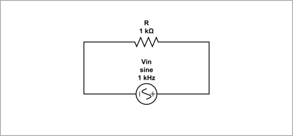
The question is conceptual. It is about the problems arising when connecting single-ended voltage sources to a differential input. The best way to understand them is to follow, step by step, the evolution of a differential input stage. For the purpose of intuitive explanation, I will represent the differential input simply through a resistor R with high resistance (1 Mohm).

Floating source and input

This is the simplest way to connect a voltage source to the device's input without using the concept of ground. For this we need two connecting wires.
schematic

simulate this circuit – Schematic created using CircuitLab

Grounded source and input

In electrical circuits, however, we use a clever trick - we connect one end of all elements (input source, feedback network, output, load, etc.) to a common wire that we call "ground" (as they say, "the input voltage source and device's input are single ended"). In this way, we connect the device's stages with only one wire and talk about "voltage at a given point". This connection technique is widely used in cars where the body serves as a ground.

Notice that the devices are still connected by two wires, only one of the wires is common to all devices. This also leads to some limitations in connection - devices cannot be connected in series (to be "floating"); they can only be cascaded in a parallel manner.

Right-grounded source and input

Thus, if we ground the right terminals of both source and resistor from the figure above, we can drive the resistor from the left.

schematic

simulate this circuit

Fig. 2 - graphics

Left-grounded source and input

And, if we ground the left terminals of both source and resistor from the first figure above, we can drive the resistor from the right.
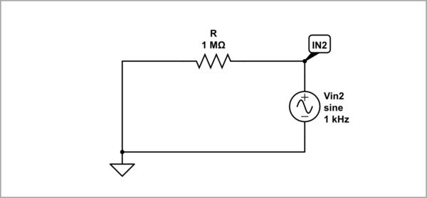
schematic

simulate this circuit

Fig. 3 - graphics

So in both cases the input (resistor R) is connected through one of its ends to a "stiff" ground and the entire voltage is applied to the input.

Grounded sources and floating input

Above we drove a grounded device input by a grounded input voltage source. But what do we do if the input is floating and we still want to drive it with a grounded input source? How do we drive a floating input with a grounded source?

Conceptual circuit

We can apply another clever trick - we can "split" the floating source in the first figure above and ground the midpoint between the two "sub-sources".

Thus we arrive at the idea of ​​differential input - to drive the input simultaneously on both sides using two grounded (single-ended) voltage sources. Actually, they are connected (through the ground) in series; so their voltages are summed (subtracted) according to KVL and the total voltage is applied to the resistor as in the first picture.

Let's implement this arrangement but now with the help of a slightly unusual "resistor" - a potentiometer. It is the same resistor as the one above, only with the help of its wiper we can observe the voltage at any point inside it.

schematic

simulate this circuit

Common mode

Vin1 = Vin2 = var. If we vary both input voltages in the same direction with the same rate, all the local voltages inside the resistor, including the midpoint (wiper's voltage), will be the same. There is no ground (the input is not grounded); there is no input voltage applied across the resistor... there is no current flowing through it. Each of the input sources "sees" an infinite resistance; it "has the feeling" that the circuit is open. This is the well-known and extremely useful phenomenon "bootstrapping".

Fig. 4_1 - graphics Fig. 4_2 - graphics Fig. 4_3 - graphics

Differential mode

Vin1 = var; Vin2 = 0 (single-ended differential mode). The right end of the resistor is grounded. This is the same case as in the second figure above.

Fig. 5_1 - graphics

Vin1 = 0; Vin2 = var (single-ended differential mode). The left end of the resistor is grounded. This is the same case as in the third figure above.

Fig. 5_2 - graphics

Vin1 = -Vin2 = var (differential mode). If we vary both input voltages in an opposite direction with the same rate, the local voltages inside the resistor will gradually decrease from the higher to the lower voltage. Because the two voltages are of opposite polarity, a point of zero voltage will appear inside the middle of the resistor; this is the famous "virtual ground". So the input is virtually grounded with its middle point. Twice as much voltage is applied to the resistor, the current is twice as much, and the resistance "seen" by each of the input sources is half the total resistance of the resistor.

Fig. 5_3 - graphics

Vin1 + const = -Vin2 + const = var (single-ended + differential mode). Now let's "lift" the two input voltages with a constant voltage of 2 V and change them differentially with amplitudes of 1 V. In practice, this means including an offset of 2 V in the corresponding field of the source parameters.

Since the two equal but opposite constant voltages are connected (through the ground) in series, they are subtracted and their sum across the resistor is zero. Conversely, the two varying input voltages are summed and their sum appears across the resistor like in the pure differential mode.

So, there is a "shifted" ground inside the resistor (at the middle point).

Fig. 5_4 - graphics

Differential pair

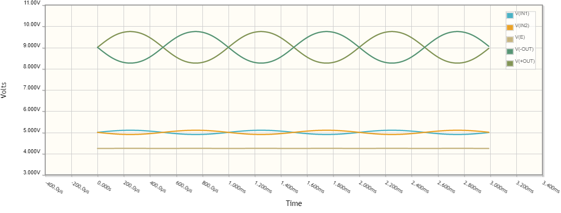
Finally let's make a connection with the differential pair that is used in the op-amp input stages. Here the two input voltage sources are buffered by emitter followers (Q1 and Q2). Their outputs (emmiters) are connected (coupled) through the emmiter resistances Re1 and Re2 to the common emitter point E.

As you can see, this is the same arrangement as the discussed above, only that the voltage difference is converted by the transistors into currents and transferred to the collectors where, with the help of the collector resistors, is converted back into voltages.

schematic

simulate this circuit

Fig. 6 - graphics

I have set an offset (input common-mode) voltage of 5 V and AC (differential) voltage of 100 mV. The phase of Vin2 is 180° (inverted). The output common mode voltage is 9 V.

An experiment with a real ground

If, after the written above, you are not convinced of the need for a "movable ground", I suggest you check it experimentally by connecting the common emitter point E to the real ground.

Differential mode

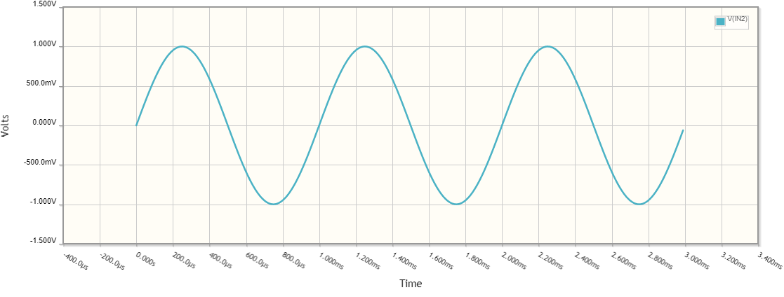
First explore the original (ungrounded) differential pair by setting the voltage of the common emitter point E equal to zero. To do this, set the offset of both input voltage sources to about 0.8 V (I have adusted it to 0.758 V).
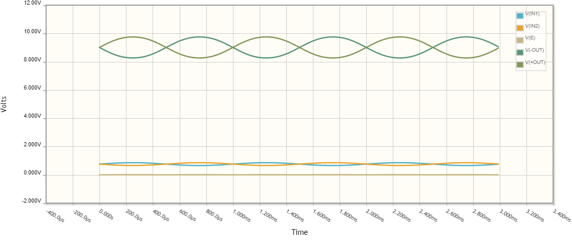
Fig. 7_1 - graphics

Then connect the point E to the real ground.

schematic

simulate this circuit

Fig. 7_2 - graphics

As you can see there is no difference between the two graphs. The two transistors work as common emitter stages with really grounded emitters. The conclusion is that the pure differential mode allows grounding of the emitter point E.

Differential + common mode

Now set 5 V offset (common mode) voltage to both input voltage sources. The result is obvious - because of the excessive base-emitter voltages both transistors are saturated. The conclusion is that the common mode does not allow grounding of the emitter point E; it needs a "flexible" ground.

Fig. 7_3 - graphics

Conclusion

In a differential stage (which is the op-amp input stage) there is no fixed ground. All three cases are possible - there is no ground at all, there is a real ground (zero) or it is shifted (in a positive or negative direction).

\$\endgroup\$
0

Your Answer

By clicking “Post Your Answer”, you agree to our terms of service and acknowledge you have read our privacy policy.

Not the answer you're looking for? Browse other questions tagged or ask your own question.