1
\$\begingroup\$

I bought a string of lights made of white LEDs (SÄRDAL by that famous Swedish company) that doesn't have an on-off switch. The AC/DC converter directly plugs into the mains (220V) and I wanted to add a switch to turn it off without having to unplug it.

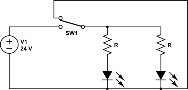
I bought a very simple switch from the hardware store and installed it on the leads that make up the string of lights, after the adapter since this was my only option. There are two leads on the string, and they run on 24VDC.

The switch is made so that one of the leads is interrupted mechanically when in "off" state, but the other lead is directly connected from one end to the other end of the switch by a strip of copper.

I thought this should be enough to interrupt the circuit and turn the LEDs off, which is mostly does, except some of the LEDs still light up very faintly in the "off" state.

When in the off state, I measure a very slight negative DC voltage between the two leads with my multimeter (as opposed to positive 24V when on).

Why is that? I thought it might be due to the two leads being twisted in a double helix way along the length of the string of lights, acting as inductors? Or maybe the electrical insulation between the two leads is not thick enough?

I tried connecting the negative lead to the terminals within the switch that are directly connected together (and the V+ wire on the interrupted side), as well as connecting the V+ lead to those and interrupting the negative wire, but both options still produce a faint light.

Thanks.

EDIT: this might not be important, but the LEDs are connected in parallel (I think), since there are 3 leads between any two LEDs, even though only two leads come out of the adapter.

\$\endgroup\$
17
  • 1
    \$\begingroup\$ Do your plugs allow you to reverse the connection? (I'm curious if the problem goes away when you mechanically interrupt only the opposite lead.) If so, there is an earth ground problem of some kind, I imagine. \$\endgroup\$
    – jonk
    Commented Jan 31, 2017 at 8:10
  • \$\begingroup\$ Hey @jonk. The switch allows me to interrupt either lead, and I did as stated in the question, but to no avail. \$\endgroup\$
    – beeb
    Commented Jan 31, 2017 at 8:15
  • 2
    \$\begingroup\$ You MAY be getting capacitive coupling. Try adding a load resistor across the LEDs on the "cold" side of the switch. Probably a 1k resistor should be low enough - or a 24V light bulb or 2 x 12V bulbs. (These would light when powered but serve to demonstrate if a load helps. \$\endgroup\$
    – Russell McMahon
    Commented Jan 31, 2017 at 8:31
  • 1
    \$\begingroup\$ the very slight negative DC voltage between the two leads with my multimeter indicates ac hum or CM AC field is present and the +V side is conducting thus lower peaks leaving a slight negative DC false reading. (not true RMS), grounding DC is one way to fix it another is a 0.1uF cap or R across LED strip. \$\endgroup\$
    – D.A.S.
    Commented Jan 31, 2017 at 8:53
  • 1
    \$\begingroup\$ A schematic would really help here. \$\endgroup\$ Commented Jan 31, 2017 at 10:13

2 Answers 2

1
\$\begingroup\$

While this doesn't answer why this is happening, you could wire your switch like this to stop the LEDs illuminating when switched off.

schematic

simulate this circuit – Schematic created using CircuitLab

\$\endgroup\$
3
  • 1
    \$\begingroup\$ If the OP has bough a typical inline switch (torpedo switch) such as might be installed on a mains lamp, it wont have the contacts to do this. I've never seen an SPDT switch in such a package (though there's probably a reaons for them to exist) \$\endgroup\$
    – Chris H
    Commented Jan 31, 2017 at 10:40
  • \$\begingroup\$ Exactly what he said, I can't do it with the switch like it is currently. I guess I could modify it, I might try this at some point when I have time. \$\endgroup\$
    – beeb
    Commented Feb 10, 2017 at 9:34
  • \$\begingroup\$ Is there some reason with your set up that you can't install the switch in the mains power cord? I am assuming the LEDs don't glow when you unplug them? \$\endgroup\$
    – LsD
    Commented Jul 20, 2017 at 13:53
0
\$\begingroup\$

schematic

simulate this circuit – Schematic created using CircuitLab

Another solution is add ferrite donut or clam shell core ferrite like that used on Laptop charger DC cables, Video cables etc.

\$\endgroup\$
3
  • \$\begingroup\$ Thanks for your answer. I finally got time to check this out, and adding a ferrite donut didn't help unfortunately. I'm gonna try other solutions now. \$\endgroup\$
    – beeb
    Commented Feb 10, 2017 at 9:31
  • \$\begingroup\$ It should have beeen large enough to wind many turns around donut, then small ceramic cap to shunt noise for series paired wires in donut \$\endgroup\$
    – D.A.S.
    Commented Feb 11, 2017 at 1:46
  • \$\begingroup\$ Okay I will try with the cap, but the donut I have can only hold the wires twice around. I'll see if I can get my hands on a larger one. \$\endgroup\$
    – beeb
    Commented Feb 12, 2017 at 19:33

Your Answer

By clicking “Post Your Answer”, you agree to our terms of service and acknowledge you have read our privacy policy.

Not the answer you're looking for? Browse other questions tagged or ask your own question.