3
\$\begingroup\$

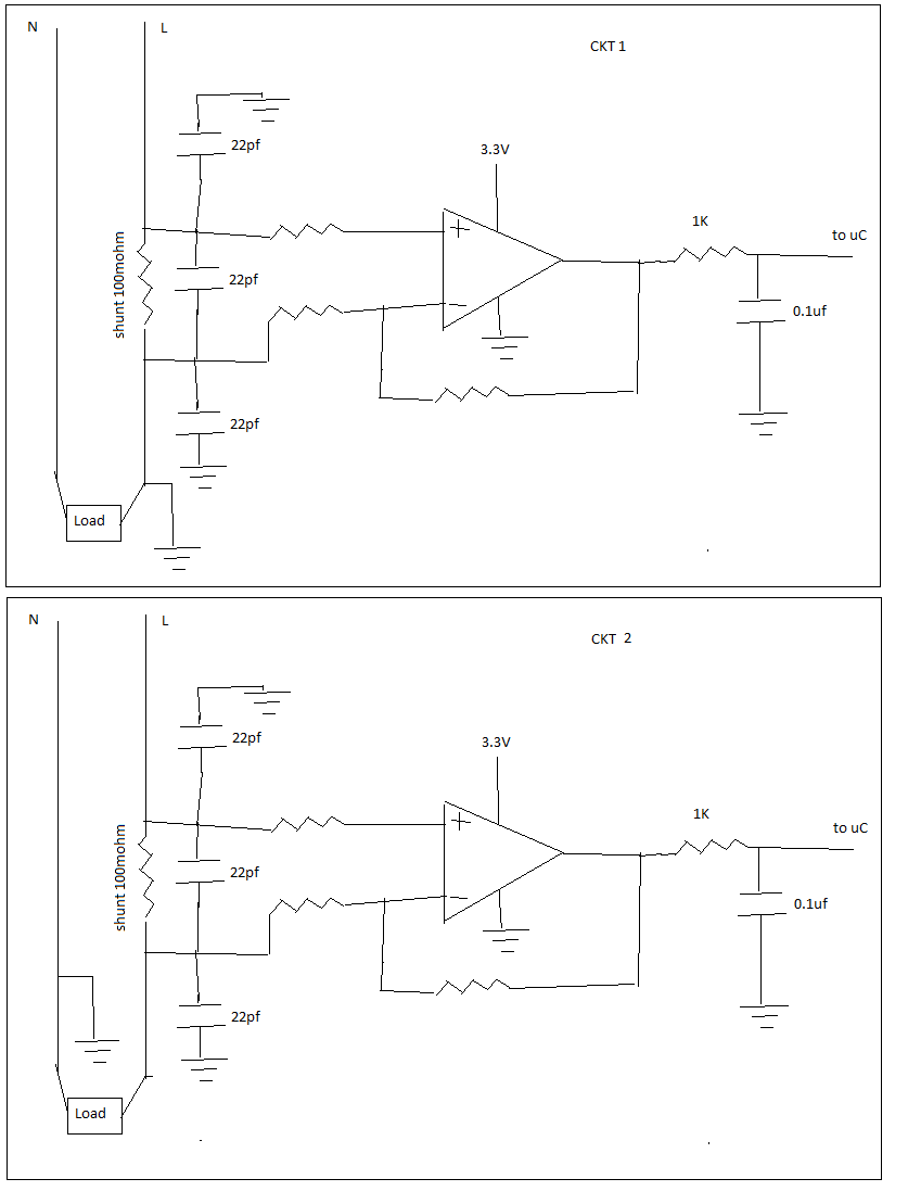
I need to measure AC RMS current using shunt resistor. AC current range is 0-8A RMS. Shunt resistor chosen is 100 mohm. which gives me max 8*1.414*10=1.13 Volt that i will use to feed an opamp to further amplify it to around max 3V with proper gain setting. and that will go to my micro controller ADC ( 0 to 3V only). Since in my circuit only positive supply is there so I used single supply op amp, (Negative half cycle will be chopped by opamp, i think). below is the ruff circuit.

which circuit out of below two looks ok to start.

enter image description here

\$\endgroup\$
11
  • \$\begingroup\$ it depends what you mean by your ground symbol. CKT1 looks rather hazardous, earthing the live terminal. \$\endgroup\$
    – Neil_UK
    Commented Feb 1, 2017 at 17:21
  • \$\begingroup\$ What is the AC voltage? If it is mains voltage, you need to rethink your entire approach. I don't think you will want to use a shunt. Probably you should use a current transformer or a Hall effect current sensor (such as ACS712) with an isolation rating. CKT2, in particular, directly connects full load voltage across your bottom 22pF capacitor. You certainly don't want to do that. \$\endgroup\$
    – user57037
    Commented Feb 1, 2017 at 17:24
  • \$\begingroup\$ If you must use a shunt, it should be on the N side. You can capacitively couple the shunt voltage to your amplifier. But this seems like a potential safety hazard, depending on what you are trying to do. It might help to provide more background on what you are doing. \$\endgroup\$
    – user57037
    Commented Feb 1, 2017 at 17:26
  • \$\begingroup\$ its 230V AC line voltage, need low cost solution , thats why i used shunt resistor, CT is bit costly here, also i can not use shunt on low side since load is outside the unit. \$\endgroup\$
    – Bharav
    Commented Feb 1, 2017 at 17:28
  • 1
    \$\begingroup\$ @user287001, putting the shunt on the neutral would be safer in practice because both sides of shunt would PROBABLY not shock you under normal conditions if you touched them. You would still have to design for total isolation. Would not change the design requirements. \$\endgroup\$
    – user57037
    Commented Feb 1, 2017 at 19:41

2 Answers 2

2
\$\begingroup\$

First: Your uC will get galvanic contact to AC mains. It will be quite a stunning effect to notice it suddenly during the use, if not taken into the account from the beginning.

The whole uC system must be safely insulated without any reachable circuitry. This is a challenge until it is battery powered and no external devices are connected otherwise than wirelessly.

If you had placed the sense resistor to N wire and secure the system to stay like that, the insulation requirements would be lesser. Unfortunately you have no way to quarantee the polarity to stay and the N-wire to be unbreakable. Thus in practice no insulation relief would be available.

At least consider to have a current transformer or a current clamp (=transformer or Hall-effect) to break the galvanic contact to AC mains. It shoud be no problem with 50...60 Hz and current this big. It solves the insulation problem instantly, because there's no galvanic contact. If the current transformer or clamp costs too much, think about an optocoupler in linear mode or a homebrew current transformer.

Second: Your differential amplifier has only 3 resistors, 4 is required if you want the result to be the current.

\$\endgroup\$
1
\$\begingroup\$

If you have to connect to a main, I would use an opto-isolator solution, right out of the gate. I've done this with a large battery bank to measure voltage and +- current. I did not want to create a ground loop with equipment and the bank. The MSP430f2013 has a 16 bit DS ADC, lot of bits. Keep your shunt down in the millivolt range and the ADC will measure negative to Vdd very well.

It is so low power that you can supply it from a simple diode/capacitor supply from the other side of the main. At that, TI has a line of MSP430s specifically meant for this kind of work, and with 24 bits. Sub-metering made easy. What I like about the 2013 is, it comes in a dip for cheap and easy prototyping, and it is cheap. Probably cheaper than using op amps to get to some other micro without isolation. In my case I used the UART to pump a stream of data through the opto-isolator.

\$\endgroup\$

Your Answer

By clicking “Post Your Answer”, you agree to our terms of service and acknowledge you have read our privacy policy.

Not the answer you're looking for? Browse other questions tagged or ask your own question.