2
\$\begingroup\$

I want to use a boost converter which will convert [email protected] to 12v@1A i.e. 12Watts. I have collected different IC's datasheets by looking at the "Efficiency vs Output current" graph.

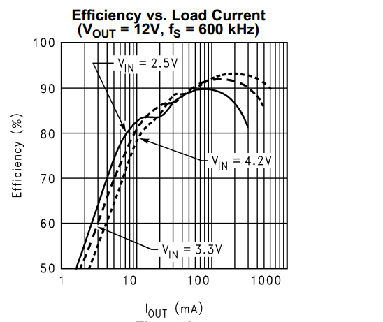
I am confused with "Switching current limit". e.g I am looking at the datasheet of LM2700 in which the "Efficiency VS Iout" graph shows approx ~85% @ 12|1amp (Vin 3.3v) which is acceptable for my application (screenshot is attached here).

enter image description here

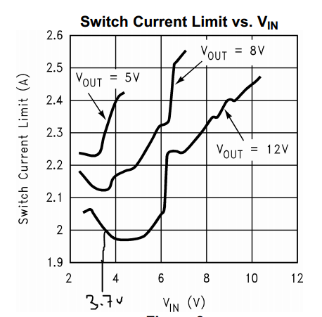
But when I viewed the "Switch Current Limit VS VIN" curve; it shows that when Vout=12v, switching current is less than 2A (screen shot is attached here).

enter image description here

And my switching current is about >3.4A (i.e. >12W/3.6v). So this will not work for me? But how did they provide the "Efficiency VS Iout" curve at 12v@1A (Vin=3.3v) in the first place when this regulator isn't able to handle that much "switching current"? Maybe I am missing something.

I would be glad if someone can clear this point to me. Thank you.

\$\endgroup\$
1
  • 1
    \$\begingroup\$ Look at the curve - it nosedives above 200mA and stops at 500mA. Which corresponds to almost 2A at 3.3V in, or about 2.4A once you factor in the efficiency. (1000 on the X axis refers to the fourth decade line, i.e. the right hand side of the graph - it's not very well labelled) \$\endgroup\$
    – user16324
    Commented Feb 8, 2017 at 12:20

2 Answers 2

2
\$\begingroup\$

I want to use a boost converter which will convert [email protected] to 12v@1A i.e. 12Watts.

  • Power in = 3.6 V x 3.4 A = 12.24 watts
  • Power out = 12 watts
  • Required efficiency is 12/12.24 = 98.04%

You need to revise your expectations because you'll be lucky to get consistently over 90% from a boost converter.

Peak switching currents and average load currents are not the same. The graph with a 3.3 volt supply and a 12 volt output is for a maximum load current of 500 mA. The graph's X axis ends at 1 amp and maybe you have misinterpreted this?

So, with a 6 watt output and a 3.3 volt input supply, the average current taken from the 3.3 volt supply is 1.82 amps (100% efficient) which rises to about 2.14 amps at 85% efficiency and broadly in-line with your 2nd graph.

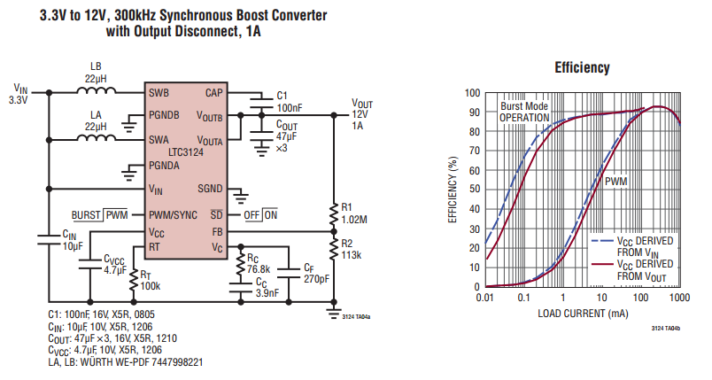
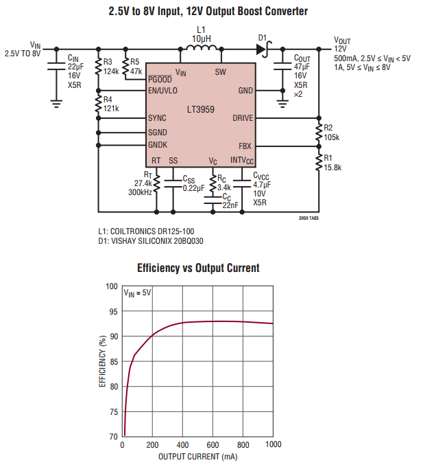
To get 12 volts and 1 amp from a 3.6 volt supply you should consider either of these (or similar ones from other suppliers): -

enter image description here

enter image description here

\$\endgroup\$
8
  • \$\begingroup\$ Thank you for the reply. Input is 12w/3.6v => 3.33w; I have actually round that figure in the above post to ~3.4 (sorry for that). And you are correct, I have misinterpreted the graph. But can I use my imagination to speculate the efficiency for 3.6V for this particular IC ? I think, Vin=3.6v curve will be between 4.2v and 3.3v curve I will end up around ~81% efficiency? Correct me if i am wrong \$\endgroup\$ Commented Feb 8, 2017 at 9:20
  • \$\begingroup\$ 3.33 watts? Do you mean 3.33 amps? \$\endgroup\$
    – Andy aka
    Commented Feb 8, 2017 at 9:25
  • \$\begingroup\$ 3.33 amps , 12watts \$\endgroup\$ Commented Feb 8, 2017 at 9:31
  • \$\begingroup\$ I would speculate that efficiency is approaching maybe 88% for a 3V6 supply creating 12 volts at 500 mA load current (but this also depends on choosing a really good inductor). I don't see the 81% you get. \$\endgroup\$
    – Andy aka
    Commented Feb 8, 2017 at 9:41
  • \$\begingroup\$ I am imagining it for 1A current load. Not 500mA. If it approaches 1A@12v | Vin=3v6; I think it will be around ~81%; but that will be useless if the switching current of LM2700 is less (as shown in the above graph i.e. <2A) and I need around ~3.4A \$\endgroup\$ Commented Feb 8, 2017 at 9:50
2
\$\begingroup\$

If you look carefully at the efficiency versus load current graph, you'll see that with a 2.5v supply, the curve stops at 300mA output, with a 3.3v supply it stops at 500mA, and doesn't go beyond 600mA with a 4.2v supply.

I'm not sure where you get the idea that the LM2700 should be able to source 1A from.

Bear in mind those are typical curves, so you may get less. The minimum guarranteed switch current is 2.55A, but that's specified at 0% duty cycle, and 2.7v, so you may well get less at a different input voltage and finite load. That squares up with the switch current limit graph you've shown.

\$\endgroup\$
8
  • \$\begingroup\$ I am using a lithium 3.6v battery as a source to generate 12v. LM2700 datasheet says that it has 3.6A internal switch, so i thought I can use this to generate 12v@1A output at around 80~84% efficiency \$\endgroup\$ Commented Feb 8, 2017 at 9:23
  • \$\begingroup\$ Data sheets sell you the sizzle of the sausage, '3.6A internal switch, yay! gotta get me some of that'. Unfortunately you have to read in detail to see what the guaranteed figures are, and when their 'typical' figures are at different volts/amps to where you want to use it. Read the data sheet to see how much meat, fat, connective tissue, bread, salt and colouring is in that sausage that sizzled so nicely. \$\endgroup\$
    – Neil_UK
    Commented Feb 8, 2017 at 10:14
  • \$\begingroup\$ Thank you Neil_UK7 for your helpful suggestion. I am reading the datasheet of ADP1614 regulator now. \$\endgroup\$ Commented Feb 8, 2017 at 10:24
  • 1
    \$\begingroup\$ looks better, but check out figures 4 and 7, 10v and 15v efficiency curves only just scrape to 1A \$\endgroup\$
    – Neil_UK
    Commented Feb 8, 2017 at 12:23
  • 3
    \$\begingroup\$ As a political compromise to keep the bloodshed to a minimum, engineering let the marketing trolls write the front page of the datasheets. Everyone else ignores them. \$\endgroup\$
    – Dan Mills
    Commented Feb 8, 2017 at 13:24

Your Answer

By clicking “Post Your Answer”, you agree to our terms of service and acknowledge you have read our privacy policy.

Not the answer you're looking for? Browse other questions tagged or ask your own question.