2
\$\begingroup\$

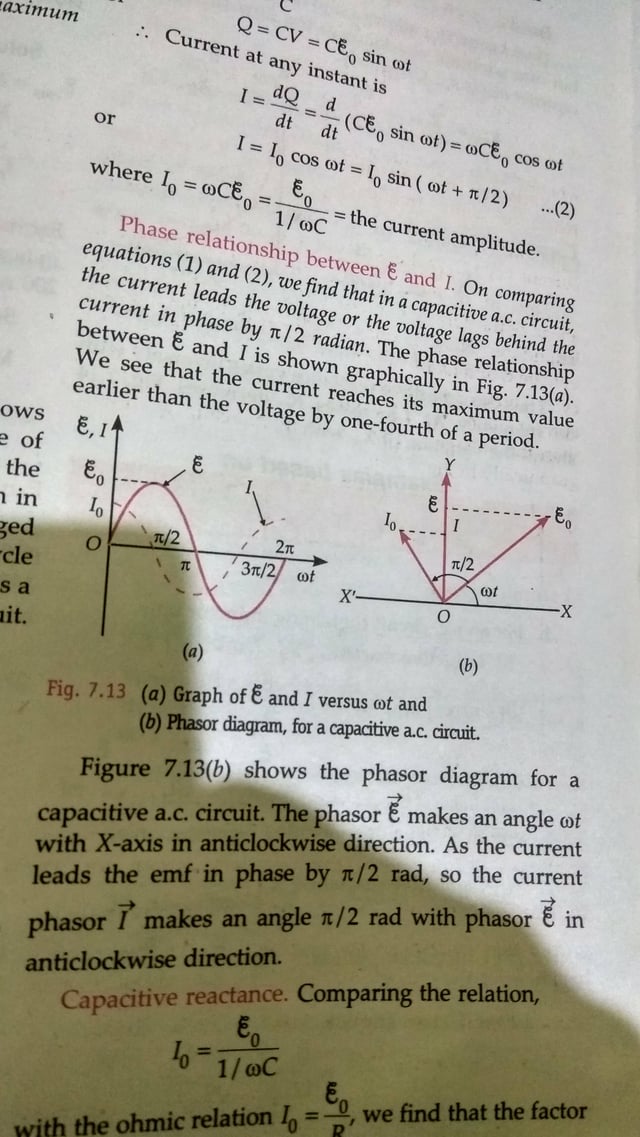
In my book, it is written that at any instant,

PD across the Capacitor Plates = Applied EMF ---------(1)

enter image description here

Assuming that it's a pure Capacitor of Capacitance C, I think if Voltage across Capacitor becomes equal to the Applied EMF then, it means that the capacitor is fully charged and thus, no current will flow.

Also, how can it be true that the given statement (1) is true at any instant?

As per the Phasor Relationship between Applied EMF and Current in Circuit, the Current is 0 at π/2 and at odd multiples of π/2 where the Applied EMF corresponds to its Peak Value.So Capacitor becomes fully charged at these instances.

Thus, what i think:

PD across Capacitor Plates = Peak Value of Applied EMF

enter image description here

Where am I wrong?

\$\endgroup\$
1
  • \$\begingroup\$ The best way to understand a capitor in a circuit is to use the equation $$I(t) = C dV(t)/dt$$ as the charge is not a quantity that is normally analysed. Please note that in your model the current is proportional the change in charge (or voltage.) When the voltage is max, the change $$dV/dt=0$$ and that is why the current is zero. This is also why it is true for each point on the voltage curve, irrespactive of the curve shape. (Remember $$ d sin(\Theta )/d\Theta = cos(\Theta )$$ is also true for all points on the curve.) \$\endgroup\$
    – skvery
    Commented Feb 19, 2017 at 4:27

4 Answers 4

2
\$\begingroup\$

Where am I wrong?

I'm sorry to tell you you're wrong end-to-end. You're missing the whole point of the analysis (the wording of the book doesn't help either).

"P.D. across the Capacitor Plates = Applied EMF" is just a fancy (and confusing for any newbie) way to say "Let's apply an AC voltage to the capacitor and see what happens then with other magnitudes like current through it". I.e.:

schematic

simulate this circuit – Schematic created using CircuitLab

Putting things this way makes easy to answer this question of you:

[...], how can it be true that the given statement (1) is true at any instant?

Well, it's true because we're forcing it to be like that so we can see what happens then with the current through the capacitor.

Next step is finding how V and I are related. One could expect that if we force the potential between the capacitor plates to vary with time, then the current through the capacitor will somehow a similar behaviour.

We recall, as does the book, that:

$$ Q=CV $$

and

$$ I=\dfrac{dQ}{dt} $$

So with the help of a little math, finally we arrive at:

$$ I={\omega}{C}{\xi_0}\sin({\omega}t+\frac{\pi}2) $$

Which, in a mathematical sense, means that current is also sinusoidal and that there is a \$\dfrac{\pi}2\$ phase difference between V and I.

V-I relationship

However, what does it mean in a physical sense? Well, somehow your intuition about it wasn't bad after all:

the Current is 0 at π/2 and at odd multiples of π/2 where the Applied Emf corresponds to its Peak Value.So Capacitor becomes fully charged at these instances

That's it! When the capacitor is fully charged, no current flows to it. When it's fully discharged, maximum current flows to it in order to charge it. And the capacitor oscillates through those states all the time while we keep applying an AC voltage to it.

EDIT:

After reading your comment to my answer, I understand where your problem is: your mathematical approach is flawed.

You look at the instant value of \$V\$ and think than you can take an interval of time \${\Delta}t\$ small enough so \$V\$ can be considered constant, that is, \${\Delta}V{\approx}0\$. Then you assimilate this situation with DC (which is also wrong because in DC you charge the capacitor through a resistor, which is absent here) and deduce that if \${\Delta}V=0\$ then \$I=0\$ so no current flows. You then extrapolate that deduction to every possible \$t\$ and conclude that no current flows at all and that the capacitor must be fully charged at all times at the peak value of the applied EMF.

Well, this is mathematically wrong for a number of reasons:

  1. If you're dealing with intervals, then apply them to ALL magnitudes involved. Your flaw resides in considering \$I=0\$ when you should be considering \${\Delta}I=0\$ instead (which isn't true either, continue reading to see why).

  2. When looking at what happens around any arbitrary time \$t_1\$, your \${\Delta}t\$ is an increment to that \$t_1\$. The same thing goes for \$V\$ and \$I\$: your \${\Delta}V\$ will be an increment to \$V_1=V(t_1)\$, and \${\Delta}I\$ will be an increment to \$I_1=I(t_1)\$. Think of \$V_1\$ and \$I_1\$ as initial conditions at the start of interval \${\Delta}t\$. It's wrong to assume \$V_1\$ and \$I_1\$ are equal to zero. Also, it's wrong to think about \${\Delta}V\$ as the difference between the applied EMF and the voltage at the capacitor. As it has been said, there is no difference between the applied EMF and the voltage at the capacitor, it's just forced to be equal.

  3. For very small \${\Delta}t\$ intervals, you'll have \${\Delta}V{\approx}0\$ and \${\Delta}I{\approx}0\$. But that doesn't mean at all that the concatenation of time intervals where \${\Delta}I{\approx}0\$ will yield \$I=0\$ and from there conclude that "no current flows, so the capacitor must be charged and \$V\$ must be constant". It's wrong to think like that. Differential Calculus and Infinitesimal Calculus tells us how to deal with things when \${\Delta}t{\rightarrow}0\$. And someone smarter than you and me already used them to work it up for us to build upon it:

$$ I=\dfrac{dQ}{dt} $$

\$\endgroup\$
3
  • \$\begingroup\$ but if it's true at any instant then how current is flowing in the circuit. In DC, if applied emf becomes equal to the voltage of capacitor then DC stops /we say the capacitor is fully charged. In Ac if we talk about that very small instant of time(where we assume that the applied emf is constant), then the scenario is same as in case of DC. And Current should not flow. Sorry if I didn't get ur point \$\endgroup\$ Commented Feb 19, 2017 at 6:31
  • \$\begingroup\$ Now I see where your problem is: your mathematical approach is flawed. You're confused about small increments. I'll edit my answer to explain it to you. \$\endgroup\$ Commented Feb 19, 2017 at 10:58
  • \$\begingroup\$ Enric I got u. I got u. Thanks a lot. You made my day. Thank you very much \$\endgroup\$ Commented Feb 20, 2017 at 8:42
3
\$\begingroup\$

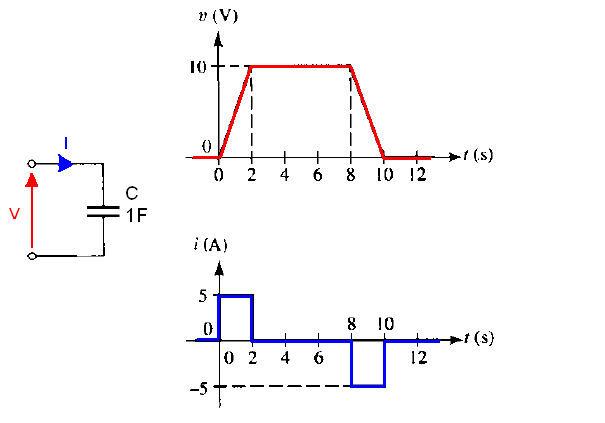
Current in the capacitor is proportional the rate of voltage change across it (proportional to how quickly the voltage across the capacitor is changing). The faster the voltage change (frequency of an AC signal is high) the large the current flow through the capacitor.

$$I = C*\frac{dV}{dt} $$

This means that to sustain current through a capacitor the applied voltage must change. The more rapidly voltage changes the larger the current. On the other hand, if the voltage is kept constant no current will flow no matter how large the voltage. Likewise, if the current through a capacitor is found to be zero, this means that the voltage across it must be constant, not necessarily zero. enter image description here

The special case is when the voltage input voltage is a sine-wave. For the sine-wave, the rate of voltage change (\$\frac{dV}{dt}\$) reaches the maximum when voltage signal crossing zero. And the rate of voltage change reaches minimum when the voltage is at a peak value.

enter image description here

enter image description here

This is why current reaches \$0A\$ because at peak the rate of change is \$\frac{dV}{dt} = 0\$ and when a input sine-wave crossing 0, the rate of change is at max \$\frac{dV}{dt} = A_{peak}2\pi f \$.

For example for \$A=1V\$ and \$f = 50Hz;C=1\mu F\$

The highest slope of the signal is \$\frac{dV}{dt} = A_{peak}2\pi f = 1V*6.28*50Hz = 314V/s\$ therefore the capacitor peak current values is

\$I = C*\frac{dV}{dt} = 1\mu F * 314 \frac{V}{s} = 0.314mA\$

And this diagram is trying to shows the charging and discharging phases for a sine-wave input voltage.

enter image description here

All this analysis assumes steady-state situation (The circuit is ON for a very long time).

\$\endgroup\$
3
  • \$\begingroup\$ I assume that you have derive this equation I=CdV/dt like this: C=q/V =>q=CV =>I=dq/dt=CdV/dt. Now V=Voltage across Capacitor Plates ; Applied Emf=e What the problem I am facing is that it's given that At any instant Voltage Across Capacitor Plates,V=Applied Emf,e. If that happens, Current which is actually 0 at odd multiples of π/2 will be 0 at every instant because the given condition V= e is only true when the Capacitor is fully charged up and thus no current flows. My question is why V=e At Every Instant rather V=e'(Peak Value of Applied Emf) \$\endgroup\$ Commented Feb 19, 2017 at 10:50
  • \$\begingroup\$ Current is flowing because the applied voltage change continuously. And the current in the capacitor is proportional to the rate of change (how fast the voltage is changing). And the derivative of sine wave is cosine wave. This is why current looks like a cosine wave. \$\endgroup\$
    – G36
    Commented Feb 19, 2017 at 11:34
  • \$\begingroup\$ @MritunJay The current through a capacitor is the derivative of the voltage across it. So try to learn what derivative is. khanacademy.org/math/ap-calculus-ab/derivative-introduction-ab/… and this allaboutcircuits.com/textbook/direct-current/chpt-13/… \$\endgroup\$
    – G36
    Commented Feb 19, 2017 at 11:45
1
\$\begingroup\$

The P.D. = \$\xi(t)\$ is a definition so it is always true.

Voltage is assumed to be sinusoidal function of time (and steady-state), so physically something (such as a function generator output) is forcing that voltage across the capacitor to be \$\xi(t)\$ = \$\xi_0 \sin(\omega t)\$.

They derive the capacitor current as a function of that applied voltage.

\$\endgroup\$
2
  • \$\begingroup\$ I think Capacitor creates it's own voltage while charging. So if it creates it's own voltage/PD and if it's equal to applied emf then current should not flow. What I think that the definition what u are saying is true if the component is consuming the applied emf like in case of Resistor where Applied Emf=IR. If I am wrong anywhere can u elaborate in detail in your answer. Thanx for ur effort and time \$\endgroup\$ Commented Feb 19, 2017 at 6:35
  • 1
    \$\begingroup\$ The voltage is forced across the capacitor. Current flows back and forth because the capacitor is continuously charging and discharging. If it stops changing, you are correct, the current would no longer flow. At the very peaks of sine wave the voltage stops changing and that is exactly where you find the current waveform momentarily passes through zero (cos). \$\endgroup\$ Commented Feb 19, 2017 at 6:58
0
\$\begingroup\$

here is how it goes. your 1st statement "P.D. across the Capacitor Plates = Applied EMF" is correct and your 2nd statement that"it means that the capacitor is fully charged " is also correct but your assumpmtion that" no current will flow" is not correct because you see in AC, voltage is incresing and decresing. charge will go into capacitor and come out of it hence current will flow eventually. hope it will help.

\$\endgroup\$

Your Answer

By clicking “Post Your Answer”, you agree to our terms of service and acknowledge you have read our privacy policy.

Not the answer you're looking for? Browse other questions tagged or ask your own question.