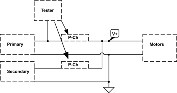
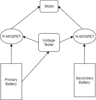
I want to build a circuit for a quadcopter where MOSFETs are connected to the primary and secondary battery. When the voltage falls below certain value in the primary battery the voltage monitor triggers the P channel MOSFET and cut the supply from primary and simultaneously the N channel MOSFET connected to the secondary battery turns ON and supplies the power. Batteries are rated 22 V Max current is 250 A.
-
\$\begingroup\$ Why a PMOS for one and an NMOS for the other battery ? That makes no sense to me but perhaps you have a good reason, if so share it. \$\endgroup\$– BimpelrekkieCommented Feb 21, 2017 at 22:02
-
\$\begingroup\$ The idea was to use one of the 1-8s voltage monitors for lipos with buzzer that indicates whether a cell has discharged below the predefined voltage. Discard the buzzer and connect the MOSFETs to it, so that when the output of the tester is high the PMOS is turned off and NMOS is turned on. \$\endgroup\$– AerluftCommented Feb 21, 2017 at 22:18
-
\$\begingroup\$ Using batteries sequentially makes no sense. \$\endgroup\$– user57037Commented Feb 22, 2017 at 4:01
-
\$\begingroup\$ The primary battery is the main supply, in order to protect the battery from overdischarge, as soon as one of the cell voltage is low the power supply should terminate and switch to the secondary. \$\endgroup\$– AerluftCommented Feb 22, 2017 at 12:30
1 Answer
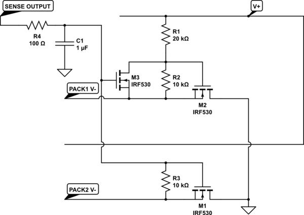
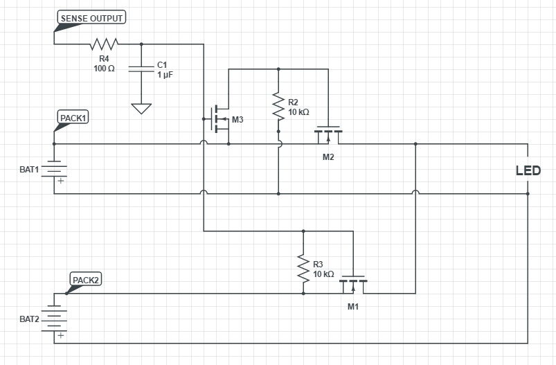
If you insist on using the batteries separately I would recommend something similar to this, although it can also be done with N-FETs on the low side

simulate this circuit – Schematic created using CircuitLab
The schematic below should work for inverting the output signal for control of the primary pack. The actual values for components should be evaluated based on actual circuit needs(Gate voltages on specific MOSFETs, filtering needs, etc.)

-
\$\begingroup\$ When the tester voltage is high, wont both the PMOS turn off? \$\endgroup\$– AerluftCommented Feb 21, 2017 at 22:22
-
\$\begingroup\$ What are you intending to use as a tester? I would recommend two outputs with one being inverted, how you choose to do this is up to you. If you are using a hardware circuit to test the voltage the inverted output can be generated with a simple FET inverter, if you are using a micro-controller or similar you can simply use two output pins. \$\endgroup\$– RedjaCommented Feb 21, 2017 at 22:30
-
\$\begingroup\$ The idea was to use one of the 1-8s voltage monitors for lipos with buzzer that indicates whether a cell has discharged below the predefined voltage. Discard the buzzer and connect the MOSFETs to it, so that when the output of the tester is high the PMOS is turned off and NMOS is turned on \$\endgroup\$– AerluftCommented Feb 21, 2017 at 22:39
-
\$\begingroup\$ I would think that the output to the buzzer is a PWM signal, which is definitely not what you want to connect to the MOSFETs, thats an easy way to burn them up. Second, the output most likely wont be equal to the primary pack voltage, which would be necessary to turn the P-FET off. I would recommend using an RC filter to ensure there is no frequency component on the output and then control the MOSFETs from the output with level shifting circuits, which are easy to find on google. \$\endgroup\$– RedjaCommented Feb 22, 2017 at 14:16
-
\$\begingroup\$ Could you please explain more about the PMOS. The primary battery input is 22V about 250 A of max current. What kind of PMOS should I select? \$\endgroup\$– AerluftCommented Feb 23, 2017 at 10:13


