5
\$\begingroup\$

Lets say we have a receiving antenna that intercepts a certain amount of power \$P_r\$ = \$SA_r\$, where \$S\$ is the power flow density of the incoming EM wave, and \$A_r\$ the effective area of the antenna. This power, \$P_r\$, is also called the available power, and is the maximum power that can be delivered to the attached load (i.e. the first stage of an RF amplifier). Maximum power transfer happens when the antenna output impedance is equal to the RF amp input impedance. Thus, we can also express \$P_r\$ the following way: \$P_r = \frac{V_A^2}{8R_A}\$, where \$V_A\$ is the open circuit voltage at the antenna port, and \$R_A\$ the antenna impedance.

The first stage of an RF amplifier can be a common emitter block, which gives us a small signal equivalent like this (under tuned conditions, assuming no feedback):
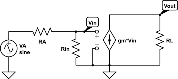
schematic

simulate this circuit – Schematic created using CircuitLab

I think it is quite obvious now, that if we power match at the input side, setting \$R_{in} = R_A\$, then we won't get maximum power transferred to \$R_L\$, since that requires maximum output current, which in turn is dependent on maximum \$V_{in}\$, which is turn is dependent on \$R_{in}\$ being much bigger than \$R_A\$. Nevertheless, I see in a lot of books that they power match the receiving antenna to the input stage of the RF amp, I just can't see why one would do it, because AFAIK doing it doesn't even imply minimum noise.

\$\endgroup\$
6
  • \$\begingroup\$ Because that first stage transistor doesn't look like a high Rin with a perfect gm stage after it (except at low frequencies)! It usually looks more like a too large capacitor in shunt with a low R. \$\endgroup\$
    – Neil_UK
    Commented Feb 24, 2017 at 21:30
  • \$\begingroup\$ Is there a feed line between the antenna and the amplifier? \$\endgroup\$
    – The Photon
    Commented Feb 24, 2017 at 21:32
  • \$\begingroup\$ True, but we can add a transformer (or transformer like circuit) to make it look higher to the source. \$\endgroup\$ Commented Feb 24, 2017 at 21:32
  • \$\begingroup\$ The Photon: No, the distance is below 1/10 of a wavelength. No transmission line. \$\endgroup\$ Commented Feb 24, 2017 at 21:35
  • 6
    \$\begingroup\$ Maximum power transfer occurs when the impedances are matched. You have to transfer maximum power to get the best signal to noise ratio. The noise floor of any amplifier depends on physical configuration and the optimum point is at maximum power. \$\endgroup\$
    – skvery
    Commented Feb 24, 2017 at 21:39

3 Answers 3

6
\$\begingroup\$

The "maximum power transferred to the load" in you example doesn't refer to \$R_L\$ at all. In fact, most of the power delivered to \$R_L\$ has not been transferred to it, but rather added by the power supply of the amplifier. Actually, the load seen by the antenna is the input impedance of the amplifier, \$R_{in}\$

So, why it's so important to maximise the power delivered to \$R_{in}\$, when this power is just a fraction of what will be delivered to \$R_L\$ at the end?

The answer is: it's all down to the internal noise of the amplifier.

The amplifier generates a certain amount of internal noise that comes from many sources within: thermal noise from noisy resistive elements, shot noise from active elements, etc.

We can characterise the noise behaviour of the amplifier with several parameters that are essentially equivalent to each other (Noise Factor, Noise Figure, Equivalent Noise Temperature, Equivalent Input Noise Power, etc.). For simplicity, I'll use the Equivalent Input Noise Power, \$P_{n,\ i}\$: the noise power that should be delivered at the input of a noiseless amplifier with the same gain, in order to generate at the output the same amount of noise power actually generated by the real amplifier.

Now we can see that, in addition to the signal power delivered by the antenna to \$R_{in}\$, we will have this equivalent input noise power \$P_{n,\ i}\$ also "delivered" to \$R_{in}\$ no matter what we do. So the only way we have for mitigating the degradation of SNR caused by \$P_{n,\ i}\$ is to maximise the transference of signal power to \$R_{in}\$.

And that is only achieved when \$R_{in}\$ is matched to the antenna.

ADDED NOTE: actually, impedance matching for truly low noise can differ from matching for maximum power transfer. This answer is just a simplification made for the purpose of illustrating the concept.

\$\endgroup\$
3
\$\begingroup\$

The reason you need to match in this way is because you need to get the most power you can to the amplifier input itself. The electromagnetic signal traveling from your antenna to your first major impedance interface (your amplifier) will reflect a significant amount of power if they are not matched.

If you suggest to make \$Z_{in}\$ bigger than \$Z_a\$, you will reflect some of the incoming power from the environment back into the waveguide/antenna as soon as it hits \$Z_{in}\$.

You're worried about getting maximum power through \$Z_L\$ , but why would that even matter if you can't even get the power to the amplifier to begin with?

Also be careful with using "R" for impedances. Impedances in antenna theory are in general complex with a real attenuation and a phase shift. Using "R" when talking about antennas/waveguides predisposes you to think about real resistances, which is not what we're dealing with. Just my two cents. Hope that helps!

\$\endgroup\$
2
\$\begingroup\$

You have a quite simplified model of an rf amp - only a resistor Rin, the magic transconductace current sink and no feedback.

Unfortunately you can't choose the Rin as you want and the feedback from the output to the input is an unavoidable fact. The Rin must be replaced by something more complex that has reactive elements, noise source and some coupling from the output, too. The gm must have some phase shift. All those things depend on the used components, their DC currents and voltages and the properties of the circuit board - all wires are circuit elements in the rf world.

Now the matching network between the antenna and the amplifier starts to get some purpose. It's a compromise between conflicting demands. The copromise must fulfill at least the following conditions:

  • stable, non-oscillating operation
  • flat enough passband response
  • high enough stopband attenuation
  • high enough total gain between the antenna and the load NOTE: the load can't be selected freely, a part of it belongs to the amplifier and the rest is the other circuitry, no use to have e resistor as the load.
  • low enough additional noise
  • simple enough circuitry
  • available parts

Often a good compromise is achieved by making the antenna (or more correctly the antenna cable) to see the combination matching circuit + the amp as the optimal load resistance for the max. power transfer.

But is it really the highest optimum - it depends how the different factors are weighted. The wighting depends on bigger things (total costs, the producibility, the wanted performance of the whole application)

The benefits of the impedance matching are so obvious that in our everyday speech the other factors are easily ignored.

\$\endgroup\$

Your Answer

By clicking “Post Your Answer”, you agree to our terms of service and acknowledge you have read our privacy policy.

Not the answer you're looking for? Browse other questions tagged or ask your own question.