5
\$\begingroup\$

Modelling a capacitor whose dielectric has resistance as a circuit element @ Physics Stackexchange


The issue of 'how to model the capacitor' arises if the dielectric of a parallel plate capacitor has a finite resistance.

enter image description here

As the diagram indicates, current can flow through the capacitor. However, this does not mean that the capacitor acts as a closed circuit. The $r$ is quite large and allows very little current through the dielectric. The current through the dielectric won't enough to prevent a charge build up on the plates. Therefore, the capacitor does not lose its capacitor related properties.

Idea #1 (capacitor with resistance = ideal capacitor and ideal resistor in series):

It might seem intuitive to pull the resistor out of the capacitor and assume that they function as an ideal capacitor and an ideal resistor separately.

enter image description here

This model will immediately run into problems because:

  1. If you use a DC source, after very long time, the potential drop across the capacitor will be equal to the E.M.F of the source. This would prevent any current from flowing. The potential difference across the capacitor is caused by the charge separation. However, as the dielectric can conduct electricity, the charge on the plates could move. This would never allow the potential difference across the capacitor to be equal to the E.M.F of the source.

Therefore, this model will fail.

Idea #2 (capacitor with resistance = ideal capacitor and ideal resistor in parallel):

After trying Idea #1, the next attempt would be to analyze if considering the dielectric resistance to function as a resistor in parallel.

enter image description here

This idea has the following problems:

  1. After a sufficiently long time, there would be a constant current in the circuit as the capacitor behaves like an open circuit. There won't be any current passing through the capacitor branch. But with the original capacitor, the charges on the plates of the capacitor can flow through the capacitor. So you cannot have a constant potential difference across the capacitor.

How do you model a capacitor which has a finite resistance?

Would I need to go scrap all the capacitance and resistance concepts and start from the fundamentals?

\$\endgroup\$
1
  • \$\begingroup\$ Note that all real capacitors are an ideal cap with an ideal resistor in parallel (and series) as lumped elements. \$\endgroup\$
    – PlasmaHH
    Commented Feb 28, 2017 at 13:39

4 Answers 4

7
\$\begingroup\$

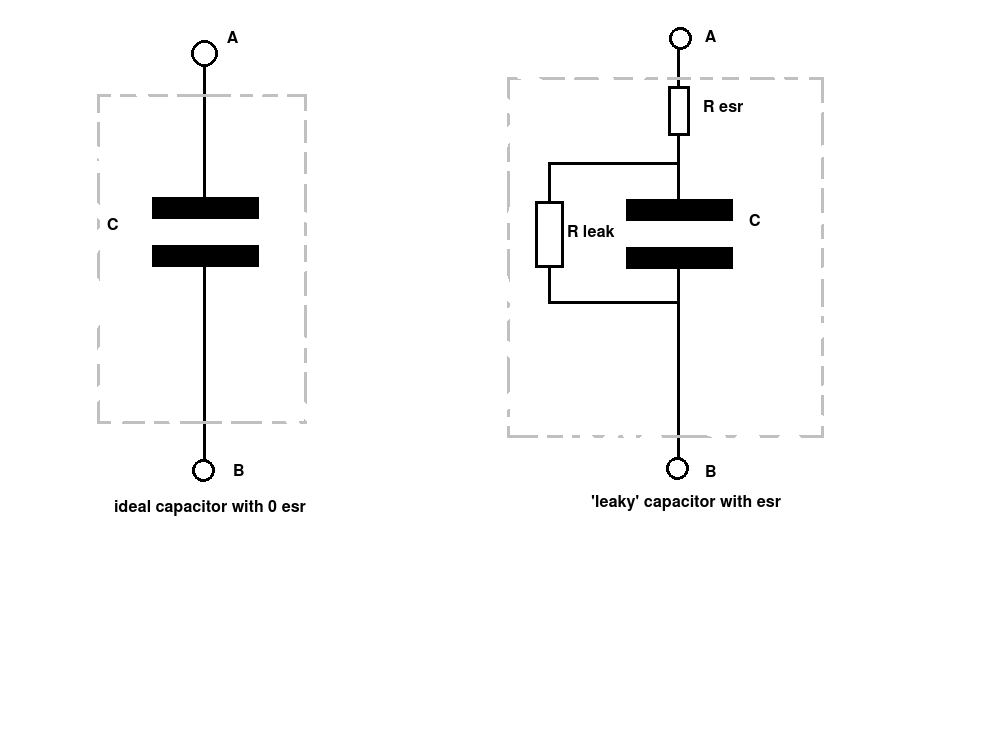
It seems you are asking how to more simply model a capacitor with "leaky" dielectric. The answer is a ideal capacitor with a resistor in parallel.

Charge up the capacitor to a fixed voltage and wait. The real capacitor will discharge slowly because of the finite resistance of the dielectric. The simplified model exhibits the same discharge due to the resistance across the ideal capacitor.

With a steady voltage applied externally, both also result in the same current, which is the voltage divided by the leakage resistance.

In general, the first order approximation of a capacitor is simply a ideal capacitor. For many uses of real capacitors, this is good enough.

The second approximation has a resistor both in series with a ideal capacitor, and one in parallel with it. The series resistance is referred to as the ESR (equivalent series resistance). This can matter in real circuits, especially when the cap is subjected to high currents.

The parallel resistance models the leakage inherent in the dielectric. This is so little (resistance so high) in ceramic capacitors that it can usually be ignored. However, leakage is more significant in other types, like electrolytic, and must be taken into account in some applications.

Note that both the equivalent series and leakage resistances can vary significantly over temperature. The leakage of electrolytic caps in particular go up significantly with higher temperature.

Of course these are all models with different tradeoffs between simplicity and fidelity. You can get really anal and make a model of a capacitor that takes into account all kinds of third order effects, like series inductance, distributed capacitance between the series inductors, between the multiple distributed series and parallel resistances, their inductance, etc, etc, etc. The more you keep going, the more you model the true behavior of any one capacitor, but the less practical the model is for designing circuits.

\$\endgroup\$
7
  • \$\begingroup\$ "After a sufficiently long time, there would be a constant current in the circuit as the capacitor behaves like an open circuit. There won't be any current passing through the capacitor branch. But for same reasons mentioned in the previous case, the potential difference across the capacitor will never reach a specific value and pretend to be an open circuit." How would you go about this issue? \$\endgroup\$
    – Yashas
    Commented Feb 28, 2017 at 14:06
  • \$\begingroup\$ @Yash: I never said what you're quoting, and it doesn't make sense anyway. It is unclear what you are asking. \$\endgroup\$ Commented Feb 28, 2017 at 16:00
  • \$\begingroup\$ If you use your model to represent the original capacitor, after sufficiently long time, the capacitor will act like an open circuit? It won't allow any current to flow through its branch. If you had the original capacitor in place instead, the charges from the plates of the capacitor could flow through the capacitor and recombine. There would be a current through the capacitor. The model won't agree with the actual case. \$\endgroup\$
    – Yashas
    Commented Feb 28, 2017 at 16:03
  • \$\begingroup\$ I think my argument is wrong. The capacitor might indeed settle at a final voltage. The current which flows through the capacitor might be due to the resistance only. At the end, there would be conduction current through the capacitor but zero displacement current. \$\endgroup\$
    – Yashas
    Commented Feb 28, 2017 at 16:05
  • \$\begingroup\$ @Yash: No, as I even stated explicitly in the third paragraph, the model with ideal capacitor and parallel resistor will draw a little current due to applied steady state voltage. \$\endgroup\$ Commented Feb 28, 2017 at 16:07
4
\$\begingroup\$

You seem fixated on this 'constant current'. Olin has given a perfectly acceptable answer so I'll try and debunk your fixation.

enter image description here

Consider two capacitors:

One ideal with infinite resistance between plates and no ESR.

The second (with identical capacitance value, C) but with ESR and a 'leaky' dielectric (= R leak). (the sort you might actually buy in the real world)

Let both capacitors be charged up to the same voltage, V, between their terminals A and B and then totally isolated from any external circuit.

Held in a vacuum, inside a Faraday cage to screen them form external fields etc.

The first capacitor (the ideal one) can neither gain or lose charge so its voltage remains constant. No current can flow between the plates.

The second capacitor (the real one) will start to lose voltage and a small current will flow between the plates as it discharges. With no current taken from the terminals there will be no voltage drop across R esr so the voltage measured at the terminals (with an ideal voltmeter) will be the voltage across the plates.

After about 5 time constants the voltage between A and B will be less than 1% of the initial voltage. ( -ln(0.01) = 4.6 = t/CR)

A small current will continue flow between the plates following the normal exponential decay of a CR circuit reducing the voltage across the plates but never reaching zero volts.

This current is NOT CONSTANT as you state. That would suggest some sort of infinite energy source with the ability to create charge (ya canna change the laws of physics, laddy!). The leakage current is always reducing with time, it is asymptotic to the axis.

What would happen if we connected an external resistor with the same value as R leak in parallel to our 'ideal' capacitor?

We would see exactly the same rate of fall in voltage at the terminals over exactly the same time with exactly the same current.

Edit update: Looking at numbers

Just to drive the point home about the size and nature of this 'leakage current by looking at the numbers.

After about 7 time constants (-ln(0.001) = 6.90775527898 = t/CR) the leakage current will be approximately 1/1000 th of the initial current. (7 makes the numbers easier to work with.)

Let's assume the initial 'leak' was 1 amp (that's one huge leakage current!) and the time constant (C*Rleak) is 1 day (that's a huge time constant!).

After just 1 week (7 time constants) the leakage will be 1mA. After 2 weeks the leakage will be 1uA. After 3 weeks the leakage will be 1nA. After 5 weeks it will be 1 fA (femtoamp) and so on - It doesn't take a genius to realise that even starting with huge numbers for leakage and time constant we very quickly get to a current value which is so small that it would be impossible to distinguish it from noise (random charge movements).

We don't get close to 'infinite time' before we are unable to measure or detect the 'leakage current'.

This 'constant current at infinity idea' is totally busted. You don't have to introduce any new concepts or change any existing concepts about capacitance and resistance.

As regards the 'ideal' capacitor.

(1) Without an external resistor it would neither gain or lose voltage regardless of time. It would simply stay charged forever with no leakage current.

(2) With the external resistor conected (R leak) to drain the charge it would behave exactly the same as our real world example, reducing the 'leakage current' to a value (in finite time) where we were unable to detect or measure it.

\$\endgroup\$
6
  • \$\begingroup\$ This was exactly my point in the question. If you make the capacitor ideal, at \$t=\infty \$, the current wills to flow through the capacitor. But this shouldn't happen as there is a conducting medium between the plates which would allow recombination of current. I am using the idea of constant current at infinity to disprove the models. \$\endgroup\$
    – Yashas
    Commented Feb 28, 2017 at 15:00
  • \$\begingroup\$ I'm sorry your language is a bit dense for me. Do you mean that the capacitor does never reach it's final voltage, because there is a voltage divider between the series and parallel resistance? \$\endgroup\$
    – Christian
    Commented Feb 28, 2017 at 15:05
  • \$\begingroup\$ @Christian The capacitor never reaches its final voltage because the charges on the plates could flow through the capacitor as the dielectric conducts. I think this argument is wrong. \$\endgroup\$
    – Yashas
    Commented Feb 28, 2017 at 16:04
  • \$\begingroup\$ I'm not making an argument, I'm trying to understand your question. \$\endgroup\$
    – Christian
    Commented Feb 28, 2017 at 16:09
  • \$\begingroup\$ If your supply resistance is high enough you are right, it would never reach the supply voltage.. But if your supply resistance is that high... you have way more problems to worry about other than dielectric conductance. \$\endgroup\$
    – Trevor_G
    Commented Feb 28, 2017 at 16:50
2
\$\begingroup\$

If we disregard the effects of the magnetic field, the potential in the capacitor will be distributed linearly from one plate to the other. That means you can just consider resistance and capacitance independently and model the capacitor as an ideal capacitor and an ideal resistor in parallel.

So what's your problem? To quote:

There won't be any current passing through the capacitor branch. But with the original capacitor, the charges on the plates of the capacitor can flow through the capacitor. So you cannot have a constant potential difference across the capacitor.

This is awfully confused. You are stating that your problem with this equivalent circuit for the real capacitor is that the ideal capacitor of the equivalent circuit does not on its own behave identically to the real capacitor represented by the circuit. But why should it? Why bother with an equivalent circuit at all if you demand that the result should be the same as one part of it?

\$\endgroup\$
1
\$\begingroup\$

After reading the various comments, I had the idea to test some electrolytic capacitors to find out if their parallel resistance \$R_{leak}\$ is constant or it is a function of the capacitor voltage.

One of the methods uses the simple formula:

$$\frac{dV}{dt} = \frac{\frac{V_m}{R_{leak}}}{{C}}$$

The slope (\$\frac{dV}{dt}\$) could be measured at the discharge starting time of a capacitor whose initial voltage is \$V_m\$.

Assuming the capacitance C is constant, if \$R_{leak}\$ is also constant, the slope (\$\frac{dV}{dt}\$) would be proportional to the initial voltage \$V_m\$. Otherwise, \$R_{leak}\$ would be a function of \$V_m\$. This reminds me how we model a non-linear inductance which is a function of the coil current.

So I will try to design a simple MCU tester to measure \$\frac{dV}{dt}\$ at different \$V_m\$ (for electrolytic capacitors only). I think I will find out that R_leak is minimum at \$V_m\$ which is close to the capacitor rated voltage and maximum close to 0V. But if the difference between the two limiting values happens to be small, one may consider that \$R_{leak}\$ is constant and equals to their average.

\$\endgroup\$

Your Answer

By clicking “Post Your Answer”, you agree to our terms of service and acknowledge you have read our privacy policy.

Not the answer you're looking for? Browse other questions tagged or ask your own question.