1
\$\begingroup\$

I'm currnetly trying to construct an electronic load for testing purposes and experimentation. This is my schematic: enter image description here
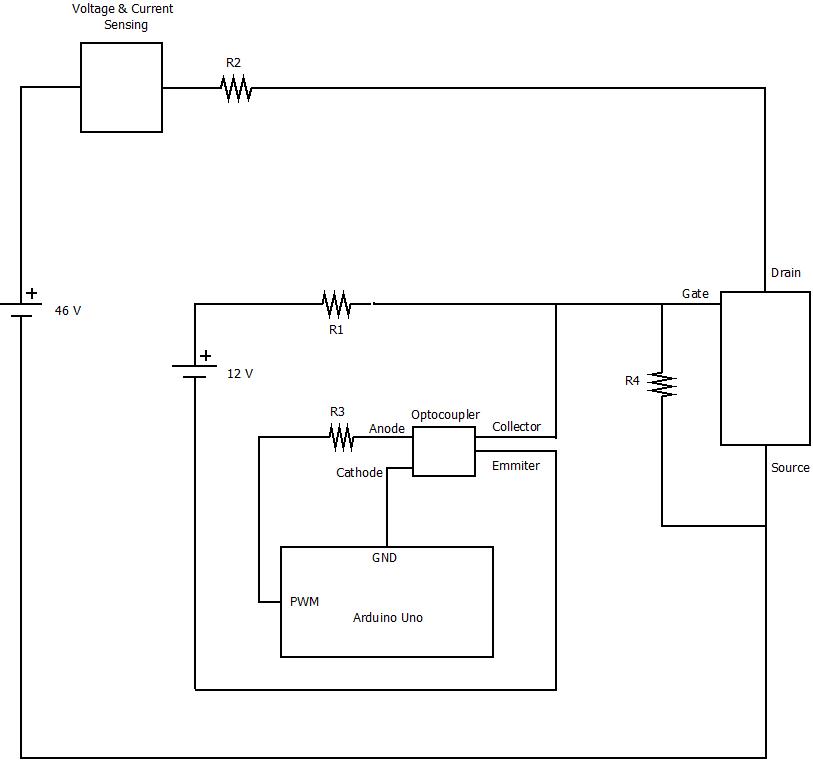
R2 are 7 X 4.7 Ω , 150 W each, resistors in parallel to cope with power up to 1kW needed. PWM is generated from an Arduino Uno, and is seperated from the rest of the circuit with an optocoupler. 12V are used for switching the Mosfets on and off. When the PWM is high 12V are sent to ground through the optocoupler and the Mosfets are off. When the PWM is low the 12V fully open the Mosfets for the duty cycle that we set. This set up is tested with one Mosfet and seems to work. However for safety reasons and not to overheat the Mosfets from the high currents and the use for long periods of time, I want to use more. A test with 5 Mosfets in parallel mounted on a heatsink was made, however resulted in the following strange result when switching on the mosfets:enter image description here
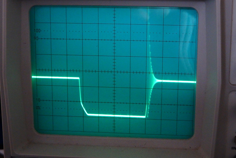
There is a strange ripple which can be seen on the oscilloscope that I can't understand the cause of it and it occurs only when switching from off to on. Is there a way to smooth things up? Thanks.

\$\endgroup\$
9
  • 1
    \$\begingroup\$ Could you put up a complete circuit and not leave important bits out like how the arduino is powered and the common grounding of supplies. \$\endgroup\$ Commented Mar 1, 2017 at 20:19
  • \$\begingroup\$ Are the grounds for the 46V and the 12V source connected together? They don't look connected to me. Also: what's the switching frequency and how are things wired together? Long wires may result in inductances that leads to behaviours like those seen in your scope trace. \$\endgroup\$ Commented Mar 1, 2017 at 20:19
  • \$\begingroup\$ Try adding a resistor 10 Ohm just before the gate. This looks like ringing to me. \$\endgroup\$
    – Christian
    Commented Mar 1, 2017 at 20:20
  • \$\begingroup\$ Your MOSFET defaults to ON when the opto/Arduino is turned OFF. Is that what you want? I would suggest moving the emitter of the opto to the gate of the MOSFET, removing R1 and connecting the opto collector direct to +12V (don't forget the ground connection others have mentioned). This will invert your PWM so you may want to rewire the LED side of the opto to turn on when the PWM pin is low. This change will actively turn-on your MOSFET, but will slow-down the passive turn-off (push-pull better as has been mentioned). \$\endgroup\$
    – Tut
    Commented Mar 1, 2017 at 21:00
  • \$\begingroup\$ The load resistors you are using could be wirewound type with inductance. Putting a flyback diode across the load resistors may clamp most of the overshoot and ringing. \$\endgroup\$
    – rioraxe
    Commented Mar 2, 2017 at 4:01

2 Answers 2

0
\$\begingroup\$

Your MOSFET turns on slowly, because it is driven through a resistor. This will increase its losses, but only if switching frequency is high enough. A push-pull driver is worth the hassle only if switching frequency is high enough to make switching losses significant compared to conduction losses. From the scope shot, I'd say switching seems to take about 5% of cycle time, however you didn't say what your switching frequency was.

Turn-off is fast because the opto shorts the gate to ground directly. Once the FET is open, it behaves like a capacitor (Cgd in datasheet). Combined with wiring inductance, this creates a LC resonant tank, which explains the underdamped resonance you see on the scope. More FETs in parallel add more capacitance, therefore more ringing.

One solution is to reduce wiring inductance, but your load resistor is probably huge considering its power, which means its inductance will be difficult to reduce.

Since you use several resistors in parallel, you could use one MOSFET per resistor. This would guarantee perfect current sharing, too.

A simple way to get rid of the ringing is to add dampening to your LC resonant tank, by adding a RC snubber across the FET. C should be a few times larger than the total Cds. As for R, the simplest way to find out is to experiment, try something between 10-100 ohms and check the scope.

You can also add a ferrite bead on the MOSFET source or drain.

\$\endgroup\$
5
  • \$\begingroup\$ My switching frequency is the Arduino default, at 490 Hz. I probably can't reduce my wiring inductance because my resistors are embedded in a metalic heat absorber. However the RC solution is easy, will try this. And the ferrite bead also. \$\endgroup\$ Commented Mar 2, 2017 at 19:08
  • \$\begingroup\$ OK! 490Hz is very low, although a resistive load won't mind at all. Now that I know the X-scale of the scope, it appears your resistor-driven FET does switch on VERY slowly. You could add more drive strength, aim for a still-slow switching time of about 1-10µs, this will ensure low EMI and low switching losses. Also at 490Hz you don't have to worry about the RC snubber heating too much, so it is probably the best solution, since your ringing seems too low frequency to be affected by a ferrite bead. \$\endgroup\$
    – bobflux
    Commented Mar 2, 2017 at 19:48
  • \$\begingroup\$ What do you mean by adding more drive strength? I've kind of lost it somewhere there. \$\endgroup\$ Commented Mar 2, 2017 at 22:18
  • \$\begingroup\$ "drive strength" is the amount of current whatever drives the MOSFET gate can output. More current means faster switching. \$\endgroup\$
    – bobflux
    Commented Mar 2, 2017 at 22:29
  • \$\begingroup\$ The best solution in my case was to reduce the number of MOSFETs used (5 was an overkill for my currents) to 2 and to use only capacitors in parallel with the mosfets without a resistor. I found on the manual of my Voltage and Current Sensor calling these capacitors bypass capacitors, and they were used to eliminate the ripples in the measurements. So I used 8.7 nF capacitors for my application, and even though it takes a little bit of time to charge them the ripples are eliminated. \$\endgroup\$ Commented Mar 13, 2017 at 19:59
0
\$\begingroup\$

First, your schematic (or circuit) probably Lacks a ground connection between your two power supplies.

Second, driving a MOSFET for power application would be better with a push-pull topology.

Third, as Enric said, how long are your wires? with those type of circuits, it they must be as short as possible.

Can you provide pictures of your test setup? this would help us a lot.

\$\endgroup\$
3
  • \$\begingroup\$ The power supplies don't have a common ground because the 46 V come from a hydrogen fuel cell that can drop its voltage to 32 V when power is needed and the 12V come from a battery for uninterrupted power. The wires heading to the resistors R2 are pretty long (~ 1 m) in order to move the heat away from the other electronics when used for long periods of time. I'll try tommorow to upload some photos of the test circuit. \$\endgroup\$ Commented Mar 2, 2017 at 19:13
  • \$\begingroup\$ even in your case the grounds must be connected. \$\endgroup\$
    – Sclrx
    Commented Mar 2, 2017 at 19:49
  • \$\begingroup\$ You were right about the grounds. I've misjudged my test setup, they were already connected. Finaly, the solution was found (see above) \$\endgroup\$ Commented Mar 13, 2017 at 19:51

Your Answer

By clicking “Post Your Answer”, you agree to our terms of service and acknowledge you have read our privacy policy.

Not the answer you're looking for? Browse other questions tagged or ask your own question.