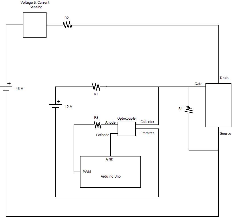
I'm currnetly trying to construct an electronic load for testing purposes and experimentation. This is my schematic:

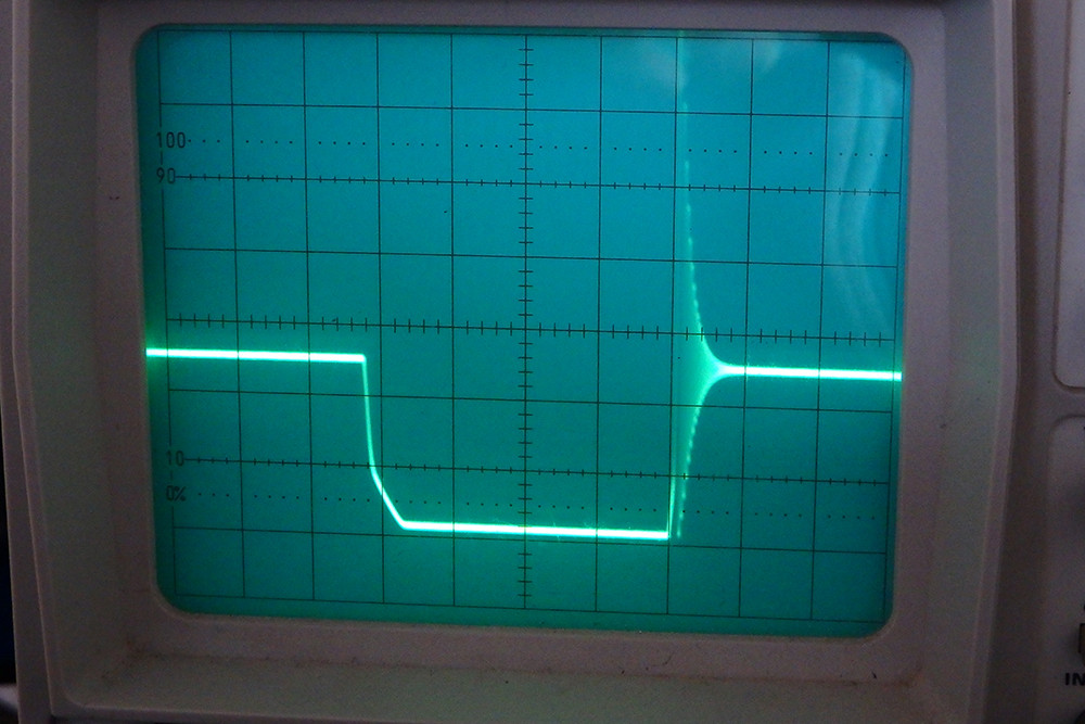
R2 are 7 X 4.7 Ω , 150 W each, resistors in parallel to cope with power up to 1kW needed. PWM is generated from an Arduino Uno, and is seperated from the rest of the circuit with an optocoupler. 12V are used for switching the Mosfets on and off. When the PWM is high 12V are sent to ground through the optocoupler and the Mosfets are off. When the PWM is low the 12V fully open the Mosfets for the duty cycle that we set. This set up is tested with one Mosfet and seems to work. However for safety reasons and not to overheat the Mosfets from the high currents and the use for long periods of time, I want to use more. A test with 5 Mosfets in parallel mounted on a heatsink was made, however resulted in the following strange result when switching on the mosfets:
There is a strange ripple which can be seen on the oscilloscope that I can't understand the cause of it and it occurs only when switching from off to on. Is there a way to smooth things up? Thanks.
