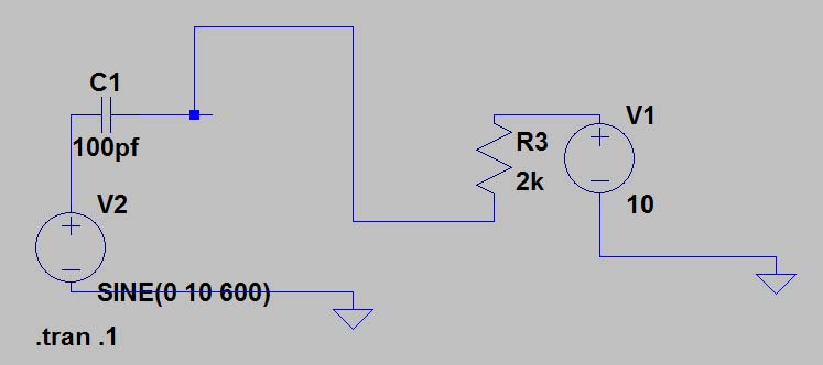
I have the following circuit in LTSPice. I can see +- 3.5 uA of current at various nodes. I should be able to calculate the 3.5 uA given the R and the C. I note that the sim output is sinusoidal. If there were no battery in the circuit, I would not be posting this question.
So what is the question....
My question is, in a simple easy to understand chunk of words, what is the effect of the battery on the circuit and why?
I understand that the capacitor will pass ac current. I understand the capacitor will block dc. I can look at the RC and frequency and can (probably) figure out how much charge the capacitor accumulates between cycles.
The basic foundation I am stuck on is the following....
At the peak of the first positive cycle, both sides of the capacitor should have 10 volts on it and hence no current or charge occurring. Battey always supplies 10 volts DC. Prior to this point, maybe it discharges? If so, where, into the ac source?
When the AC flips polarity, it looks to me like a signal rising to 10 volts is going into a battery, which looks to be in series, so 20 volts on the capacitor this time?
In ltspice, i look at the voltage between v1 and r3, it is at a constant 10 volts. I would think it should show a rise to volts?
In ltspice, i look at the voltage between r3 and c1 and it appeats to have a sinusoidal signal on it on 10 volts varion +- 15 millivolts.
Why is this sinusoidal and not showing more current (20 volts) on one side and less current (10 volts) on the other?
Thanks for some basic clarification.

