0
\$\begingroup\$

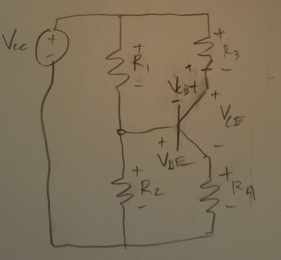
The problem is if \$\beta= 100, V_{cc} = 9v, R_1 = 16k, R_2 = 4k, R_3 =10k, R_4 = 1k,\$ solve for \$ I_b, I_c, I_e, V_b, _c, \$ and \$ V_e.\$

enter image description here I tried to rewrite the circuit here

I tried to write equations for each loop:

\$V_{cc} - (i_{R_{1}})·R_1 - (i_{R_{2}})·R_2 = 0 \$

\$-(i_C)·R_3 - V_{CB} + (i_{R_{1}})·R_1 = 0\$

\$-(i_E)·R_4 + (i_{R_{2}})·R_2 - V_{BE} = 0\$

\$V_{cc} - (i_C)·R_3 - V_{CE} - (i_E)·R_4 = 0\$

And tried to put that in matrix vector form, but ended up with a singular matrix.

What kind of approach can I use to solve this problem?

\$\endgroup\$
1

3 Answers 3

3
\$\begingroup\$

The very first thing to do is to simplify the circuit. There's an obvious first step, there. You combine \$R_1\$ and \$R_2\$ and the voltage source into a Thevenin equivalent. The resulting circuit looks like this:
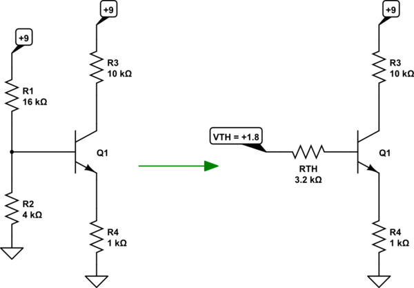
schematic

simulate this circuit – Schematic created using CircuitLab

I'm going to assume that you understand how I got the result on the right from the circuit on the left.

From there you can use your approach:

$$ V_{TH}-I_B\cdot R_{TH} - V_{BE} -I_E\cdot R_4 = 0$$

The only trick to apply here is to recognize that \$I_E=\left(\beta+1\right)\cdot I_B\$. (This will be true if the BJT is in its active region and isn't saturated.) That's something I think I can assume you also know, too. From there, you just do the obvious:

$$\begin{align*} V_{TH}-I_B\cdot R_{TH} - V_{BE} -I_E\cdot R_4 &= 0 \\\\ V_{TH}-I_B\cdot R_{TH} - V_{BE} -\left(\beta+1\right)\cdot I_B\cdot R_4 &= 0 \\\\ V_{TH}- V_{BE} &= I_B\cdot R_{TH}+ \left(\beta+1\right)\cdot I_B\cdot R_4 \\ \\ V_{TH}- V_{BE} &= I_B\cdot \left(R_{TH}+ \left(\beta+1\right)\cdot R_4\right) \\ \\ I_B &= \frac{V_{TH}- V_{BE}}{R_{TH}+ \left(\beta+1\right)\cdot R_4} \end{align*}$$

There are some small details to worry about. The above is just a rough approximation. You need to make some estimate about \$V_{BE}\$ for the transistor and no matter what you do, it will remain the case that your estimate is, at best, just an estimate. You also need to guess at the value of \$I_C\$ as a first approximation. The nice thing is that after your first guess you get a value which is much better and you can plug that in one more time and almost always stop at that point with more than sufficient results.

Instead, you could plug in the Ebers-Moll model equations for the transistor. Then you could compute it through a closed solution that involves the product-log function (aka the Lambert-W function.) But almost no one uses it except mathematicians.

Luckily, both of those guesses aren't difficult to guess at in most cases and if you remember a few rules you can get very, very close without having to write out pages of algebra.

In your case I get the value of \$V_B\approx 1.767\:\textrm{V}\$. To get it, I assumed that \$V_{BE}=700\:\textrm{mV}\$. If you know subtract the estimated \$V_{BE}\$ from that value, you will have a new \$V_E\$ value. You can then use that to esimate \$I_E\approx 1.067\:\textrm{mA}\$ and, given \$\beta=100\$, then \$I_C\approx 1.056\:\textrm{mA}\$. You should be able to proceed from there.

I mentioned another link you can look at here, where I wrote more about this. (I may yet need to correct that link, but the corrections will be slight when I do.)


NOTE: In the comments below, there's a discussion of \$r_e\$. This is usually only important as the external resistor \$R_4\rightarrow 0\:\Omega\$ and for cases where there are signal changes taking place. \$r_e\$ is the so-called dynamic resistance and it is based upon a very simple derivation from the Shockley equation. All I/V curves, no matter how complex, will look like a line if examined close enough and therefore have a local slope, given any specified operating point on that curve. In effect, \$R=\frac{\textrm{d} V}{\textrm{d} I}\$ is always a true statement when the locality of view around an operating point is sufficiently small.

However, this is dynamic and arrives only as a matter of trying to make a signal change. There is also a DC perspective at any operating point, which is always \$R=\frac{V}{I}\$ with \$V\$ and \$I\$ taken at that operating point.

\$\endgroup\$
11
  • \$\begingroup\$ jonk, your above description is purely for DC. Therefore: Why and at which step of your (rough) calculation you would make use of the small-signal quantity re=1/gm ? \$\endgroup\$
    – LvW
    Commented Mar 6, 2017 at 9:05
  • \$\begingroup\$ @LvW \$r_e\$ always exists, even in DC. I wrote about this on a different EE.SE page. Are you implying it's an AC-only parameter? If so, that's wrong. \$\endgroup\$
    – jonk
    Commented Mar 6, 2017 at 19:15
  • \$\begingroup\$ jonk, I am surprised that you think I would be wrong. The quantity you have mentioned in your text (re=kT/qIc) is nothing else than 1/gm=hie/hfe. Hence, it is a small-signal parameter which must not appear in a pure DC calculation. In other terms: gm=1/re is the slope of the function Ic=f(Vbe). The quantity beta appears because we always use beta=B. Formally, in such a DC calculation we always should use B only. \$\endgroup\$
    – LvW
    Commented Mar 6, 2017 at 20:59
  • \$\begingroup\$ I suppose such a misconception (considering re in a DC calculation) results from the unfortunate fact that some authors show such a resistor re in an equivalent small-signal diagram for the BJT. More than that, they call it "emitter resistance" which is simply false. It is no resistance (no two-pole device). \$\endgroup\$
    – LvW
    Commented Mar 6, 2017 at 21:16
  • \$\begingroup\$ @LvW Let me describe what I think you are addressing in my response above. Perhaps I take your point. \$\endgroup\$
    – jonk
    Commented Mar 6, 2017 at 22:20
1
\$\begingroup\$

You're missing some of the key equations related to the BJT, try combining these:

Equations for each Vcc to GND branches:

Vcc - I1*R1 - I2*R2 - Ib = 0 (account for I1 splitting off into base current and I2)

Vcc - Ic*R3 - Vce - R4*Ie = 0

Equation for Base Emitter Loop:

I2*R2 - Vbe = R4*I4

(Usually assume Vbe ~ 0.6V): I2*R2 - R4*I4 = 0.6V

Equations relating Ic, Ie, and Ib:

Ie = Ic + Ib

Ib = beta*Ic

NOTE: Take particular note of the second to last and last equation I have listed, which are key to solving this type of problem

\$\endgroup\$
2
  • \$\begingroup\$ Ib = beta * Ic ? surely Ic = beta * Ib \$\endgroup\$ Commented Mar 6, 2017 at 11:54
  • \$\begingroup\$ First equation: Vcc.........-Ib = 0 ? \$\endgroup\$
    – LvW
    Commented Mar 6, 2017 at 12:01
0
\$\begingroup\$

Assign the ground (=reference node) to be the minus of Vcc

Introduce the following variables

Vb = the voltage of the base (referenced to ground)

Ib = the base current into the transistor

Understand and solve the following equations

Ic = beta * Ib, downwards

Ie = emitter current, downwards, = Ib+Ic

Vc = the collector voltage = Vcc - Ic *R3

Ve = the emitter voltage = Ie * R4

Vce = the collector-emitter voltage = Vcc- Vc - Ve

Ib = (Vcc-Vb)/R1- Vb/R2

Vb = Vbe + Ie * R4: Vbe = transistor BE-junction voltage drop, 0.6V to 0.7V are typical values, take Vbe=0.65V

These are enough. To get the base current directly a seasoned hobbyist replaces the combination Vcc, R1, R2 by its Thevenin equivalent that he memorizes straight away. Its voltage VT = Vcc *R2/(R1+R2) and resistance RT= R1 parallel R2. The straigt away Ib loop equation is:

VT=Ib *RT + Vbe + (beta +1) *Ib *R4

or more fast: Ib= (VT - Vbe)/(RT+ (beta+1) *R4)

Of course this is unnecessary, but it is THE way to be fast.

Your singular matrix was resulted from inserting too many loop equations that were not independent. Every new loop equation should add something new that is not already used in other equations.

\$\endgroup\$

Your Answer

By clicking “Post Your Answer”, you agree to our terms of service and acknowledge you have read our privacy policy.

Not the answer you're looking for? Browse other questions tagged or ask your own question.