4
\$\begingroup\$

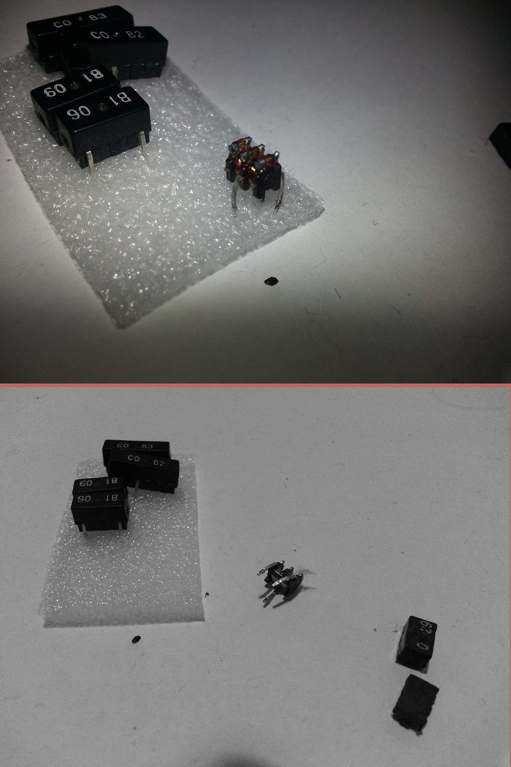
A couple of weeks ago I dissassembled a Panasonic DVD-recorder and salvage some components including these little guys. I tried to figure out what these are but cannot find a datasheet by searching for the numbers on these components.

Coil components

I decide to crack on of them open (sse picture above) to see what's inside. There is a coil, looks like a decoupling coil. At the first place I thought this could be useful to seperate audio channels (ground-isolator) but the ground seems to be shared between coils. There are three legs, input, output and ground (I guess).

So what it is used for or what can it used for? Is there a datasheet of these things somewhere? The partnumbers are (numbers on the case of the component):

  • CO 82
  • CO 83
  • B1 06
  • B1 09
  • 0 29
\$\endgroup\$
3
  • 3
    \$\begingroup\$ Could be a centre tapped coil, could be a delay line. \$\endgroup\$
    – Trevor_G
    Commented Mar 17, 2017 at 20:50
  • \$\begingroup\$ Thanks for the comment, analog or digital? Or a phase inverter? \$\endgroup\$
    – Codebeat
    Commented Mar 22, 2017 at 1:15
  • \$\begingroup\$ Delay line? Something like this media.digikey.com/pdf/Data%20Sheets/Susumu%20PDFs/… I have not seen them in that package for decades though. Could be analog or digital, they were always used in conjunction with other components or gates. \$\endgroup\$
    – Trevor_G
    Commented Mar 22, 2017 at 1:41

1 Answer 1

3
\$\begingroup\$

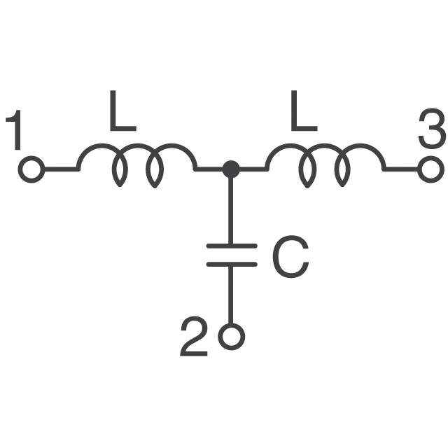
It's almost certainly a filter. Three terminal filters are common and popular, and can range from a tapped inductor, a pi filter, or an LCL filter depending. You'll likely find different values or topologies in each of those with different letters.

These are basically just potted inductors and capacitors arranged various ways, and can often be made just for a specific production run. Panasonic specifically is a large producer of these filters, so it makes sense that they would use custom parts produced just for one of their DVD drives. It's unlikely you'll find a datasheet, there probably was never a datasheet to begin with.

On the other hand, if you can measure inductance and capacitance, it is pretty easy to figure out the topology and frequency range of the filter.

Here is an example of what i mean: enter image description here

They're really not much use and you can get any sort of filter you want in a nice SMD package these days off digikey anyway. But I am sure those are just potted filters. Not the most exciting answer, sorry!

\$\endgroup\$
1
  • \$\begingroup\$ Well, this seems a very clear explained answer, I think/assume you are right. Thanks. I will throw these in the bin. \$\endgroup\$
    – Codebeat
    Commented Apr 23, 2017 at 17:31

Your Answer

By clicking “Post Your Answer”, you agree to our terms of service and acknowledge you have read our privacy policy.

Not the answer you're looking for? Browse other questions tagged or ask your own question.