0
\$\begingroup\$

I want to measure voltages of multiple cells which are connected in series. I want to do that using a differential amplifier. I read about low input impedance, and what to do about it in this case. So I found this schematic:
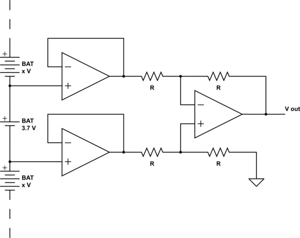
schematic

simulate this circuit – Schematic created using CircuitLab

I'm wondering, whether it's really important to have high input impedance here, because the battery has a very low resistance, so the input voltage of the OP AMP should be almost the same as the battery voltage, no? So is it indeed better, to add those two voltage followers, or stick with the simpler differential amplifier variation?

\$\endgroup\$

2 Answers 2

2
\$\begingroup\$

To answer your actual question... As long as the R values are large you do not need the buffers for it to work as you imagine. However, be aware without them there will be some drain on the battery if the R values are not as large at the op-amp input impedance.

However, what concerns me more is the stack of batteries. If you plan on doing this for every battery in the stack, and the stack is large, at some point you will exceed the input voltage on the op-amp.

\$\endgroup\$
5
  • 1
    \$\begingroup\$ If the batteries are also used to power the amplifier circuit, it won't decrease the current drain to use the buffers. \$\endgroup\$
    – The Photon
    Commented Mar 20, 2017 at 5:04
  • \$\begingroup\$ And if you power down the amplifiers to avoid that problem, their input protection diodes will drain the battery (possibly damaging the amplifiers) \$\endgroup\$
    – user16324
    Commented Mar 20, 2017 at 11:51
  • \$\begingroup\$ Thx, for the good hint about the input voltage. If I power the op-amp with two corresponding cells. I don't have to problem, right? Then I need an optocoupler to put it back to some other ground. Would that work, or do you see another problem? \$\endgroup\$
    – duedl0r
    Commented Mar 23, 2017 at 14:39
  • \$\begingroup\$ @duedl0r yes I suppose, but as you have correctly mentioned, that just brings the problem to the other side of the circuit. Since I assume you are going to read this output with an ADC, using an opto-coupler gets tedious to calibrate. \$\endgroup\$
    – Trevor_G
    Commented Mar 23, 2017 at 14:56
  • \$\begingroup\$ @duedl0r, Depending on how "accurate" you need this, it would be simpler just to select (Enable) one of N voltage dividers, one divider per battery up the stack, measure the voltage at each point and do the math to calculate the voltage across each cell. \$\endgroup\$
    – Trevor_G
    Commented Mar 23, 2017 at 14:59
2
\$\begingroup\$

The answer is (of course), it depends on how you are using this and what accuracy you need.

It is true that the internal impedance of most batteries is low, so as long as R is much bigger, the voltage drop from the battery won't be a big issue.

However, if the leads connecting the batteries to the amplifier have some non-zero resistance, this will give both gain and common-mode rejection errors in your amplifier. The buffer amplifiers solve both of these problems as well by reducing the current in the leads to near zero.

\$\endgroup\$

Your Answer

By clicking “Post Your Answer”, you agree to our terms of service and acknowledge you have read our privacy policy.

Not the answer you're looking for? Browse other questions tagged or ask your own question.