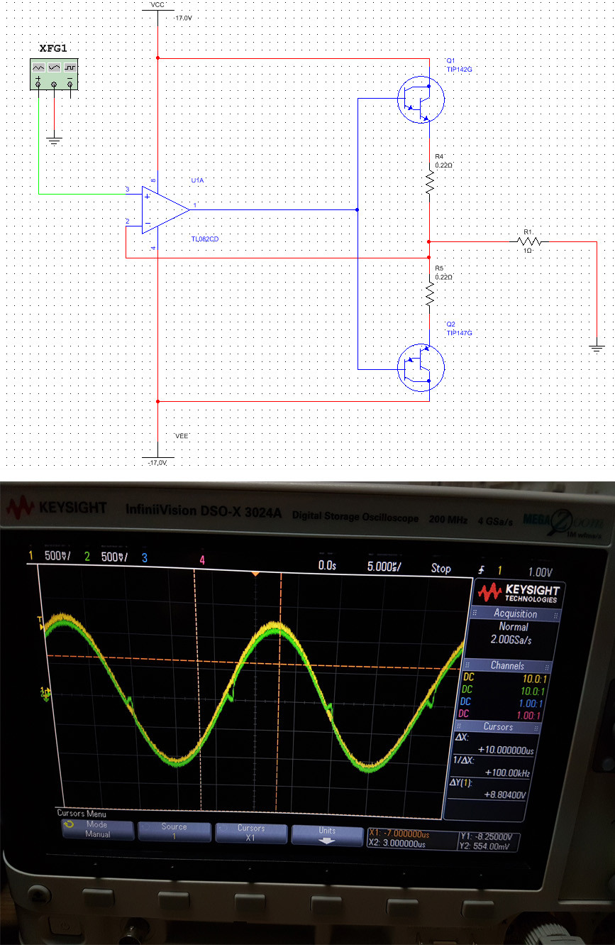
I decided to make a power DC-amplifier. I used complementary darlington pair TIP142 and TIP147. Also TL082 used for negative feedback. The schematic is as below:

I gave 100 kHz sine signal and under oscilloscope I noticed the crossover distortion. It seems opamp is too slow to compensate ±1.4V "dead zone" (distorion on oscilloscope above).
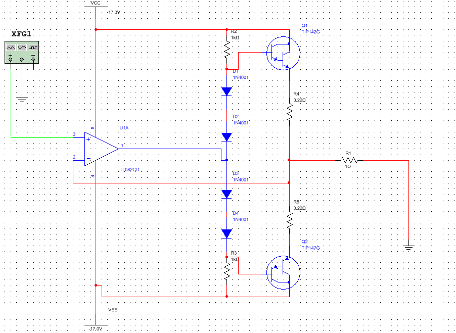
Then I decided to bias darlingtons bases using four 1n4148 diodes as follow:

Unfortunately after 5 seconds TIP147 blew up although transistors were mounted on a heat sink and the fun was over. :D
I was reflecting what actually gone wrong. I suppose that:
- I didn't put diodes on the same heat sink as darlingtons. Consequently BE voltage dropped under the diodes bias.
- In Horowitz's "The Art of Electronics" I have read if I we are using emiter resistors, then four diodes biasing are insufficient.
I would to know are my conclusions correct and also how to effectively get rid of crossover distortion.


