0
\$\begingroup\$

enter image description here

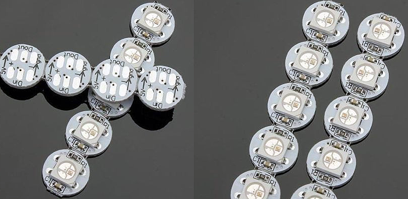
Currently i'm drawing a pcb board in Eagle. Can't get a viable solution to allow people easy handsolder this component (WS2812B). I will have 60 of this in the PCB, and i like to use them instead of RAW LED because it already contains the capacitor and resistor, so it will spare 60x4 solder joints. Also i find the price lower than source led + capacitor + resistor.

PCB is to be hand soldered like a KIT. No autoplacement machines.

My main ideia is place them at top layer and do vias to solder from bottom layer. Is it viable or there are better solutions?

Regards

\$\endgroup\$
4
  • \$\begingroup\$ Those parts really aren't designed for hand soldering, and I would not trust soldering them through vias. Your best bet would be to have the builder do a reflow process for these parts first, and then hand-solder the rest of the board. Reflow requires solder paste and a toaster oven. \$\endgroup\$
    – DerStrom8
    Commented Mar 27, 2017 at 11:43
  • 1
    \$\begingroup\$ I find it hard to believe you can't get the individual components for less than you can get assembled modules, maybe you should find a better distributor. I'm not sure what function the resistor performs, do you have a schematic for the module? You may be able to use a resistor pack to replace multiple resistors, if it's needed at all. \$\endgroup\$
    – Finbarr
    Commented Mar 27, 2017 at 11:49
  • \$\begingroup\$ Resistor is not really needed, just if want extra protection... I will go with separate components. Thanks \$\endgroup\$ Commented Mar 27, 2017 at 13:19
  • \$\begingroup\$ You're going to need a resistor to limit the current. Otherwise you'll burn out your LEDs. \$\endgroup\$
    – DerStrom8
    Commented Mar 27, 2017 at 16:05

3 Answers 3

1
\$\begingroup\$

Seems this device is designed to be cable-mounted. I very doubt people will be able to mount it onto the board through vias. There're several risks to it:

  • insufficient solder: bad connection through vias, which may break in most critical situation. I think you do not want returns and bad reputation for bad kit design;
  • too much solder: risking to short the pins, potentially frying the device.

If you'd be soldering it yourself, probably you can manage to have acceptable soldering quality (after several broken boards), but as others will be soldering it I very doubt they will gain required skill to solder them properly.

Go for separate components, even if it is more cost and more work on soldering.

\$\endgroup\$
5
  • 1
    \$\begingroup\$ I have done a prototype and cable mounted works well in fact. Since it can cause problems and misalign i will go for separate components. Thanks for all the tips \$\endgroup\$ Commented Mar 27, 2017 at 13:17
  • \$\begingroup\$ If castellated vias were used instead of normal vias I don't see any reason why you couldn't design it to be solderable. \$\endgroup\$
    – ks0ze
    Commented Mar 27, 2017 at 13:46
  • \$\begingroup\$ The existing board with LED on it does not have castellated vias. Look at the picture in the question - boards have pads at the bottom. \$\endgroup\$
    – Anonymous
    Commented Mar 27, 2017 at 13:50
  • 1
    \$\begingroup\$ Right, I'm saying do a thin strip of castellated vias on the board being developed and have a large enough cut out to get the iron in there. Essentially, reverse of how they would normally be used. \$\endgroup\$
    – ks0ze
    Commented Mar 27, 2017 at 13:54
  • \$\begingroup\$ This is actually really creative idea. @tiago-conceição may see if he has space for such board elements. May such board design increase cost of PCB and decrease its hardness? \$\endgroup\$
    – Anonymous
    Commented Mar 27, 2017 at 14:52
1
\$\begingroup\$

How big are the pads? With power pads on opamp IC's I'v'e put one or two big holes under the pad and then hand soldered to that... a big blob of solder fills up the hole.

\$\endgroup\$
2
  • \$\begingroup\$ Did you ever do it yourself by hand? I have a design where I connect bottom chip's pad (FPGA) to the ground through wide via (metallized hole). There're a lot of space under the chip, but sometimes solder shorts other tracks/vias under the chip, or just has bad contact even if it looks soldered fine from the bottom of the board. \$\endgroup\$
    – Anonymous
    Commented Mar 27, 2017 at 13:16
  • \$\begingroup\$ @Anonymous, Yeah by hand. You do have to be sure that you get contact to the plated hole and the pad on the IC. (The last one was an LTC6090.. no FPGA's.) \$\endgroup\$ Commented Mar 27, 2017 at 19:46
-1
\$\begingroup\$

You don't provide a datasheet, so I used this one:

https://cdn-shop.adafruit.com/datasheets/WS2812B.pdf

This part does not have a thermal pad under the chip, only four SMD pins, on standard SMD pads, so it will be as easy to solder as any other SMD.

I don't understand why you talk about vias. Just solder them like any other SMT part.

\$\endgroup\$
5
  • 1
    \$\begingroup\$ Look at the picture attached to the question - this part you mention is on the board, and question is about how to solder this board which hs this part on it. \$\endgroup\$
    – Anonymous
    Commented Mar 27, 2017 at 13:13
  • 3
    \$\begingroup\$ I ask if you read my whole post? Thats the RAW LED and i'm asking about a module (Look at image) \$\endgroup\$ Commented Mar 27, 2017 at 13:14
  • \$\begingroup\$ No. You ask "Handsolder this component (WS2812B)". If you want to handsolder this PCB module (not component), then say so. You need a reflow oven for this, or reflow skillet. Better to provide WS2812B not mounted on PCB modules, these will be easier to solder by hand. \$\endgroup\$
    – bobflux
    Commented Mar 27, 2017 at 13:22
  • 2
    \$\begingroup\$ @peufeu All you had to do was read the original post and look at the image to see you were making a mistake. The OP was very clear about his intent. \$\endgroup\$
    – DerStrom8
    Commented Mar 27, 2017 at 16:07
  • \$\begingroup\$ @peufeu I was more than clear, and i post a image at first, just because i write "component" theres no need to reply like you did, i bet you understand my intent at first place, still you come with a smart anwser. Anyway the situation is already solved. Thanks \$\endgroup\$ Commented Mar 28, 2017 at 23:43

Your Answer

By clicking “Post Your Answer”, you agree to our terms of service and acknowledge you have read our privacy policy.

Not the answer you're looking for? Browse other questions tagged or ask your own question.