1
\$\begingroup\$

I'm connecting many momentary switches to a IO expander, like the MCP23017:
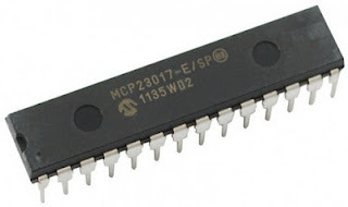
.

I read that I need to put pull-up resistors for each switch connected to the MCP23017. On another place (datasheet), I read:

GPA1 Bidirectional I/O pin. Can be enabled for interrupt-on-change and/or internal weak pull-up resistor.
GPA2 Bidirectional I/O pin. Can be enabled for interrupt-on-change and/or internal weak pull-up resistor.

Question: do I really need to add resistors myself between the IO expander and the switches or not?


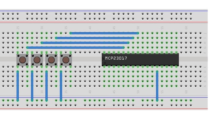
Note: Here is how I would connect the tact switches to MCP23017 (which is then connected to a Raspberry Pi): will this work, without any external pull-up resistors?
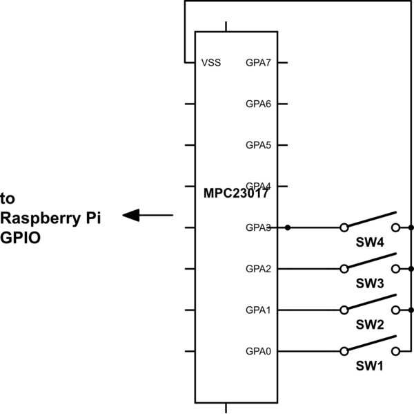
schematic

simulate this circuit – Schematic created using CircuitLab

enter image description here

\$\endgroup\$
4
  • 1
    \$\begingroup\$ "some place on the internet" vs "the official datasheet". Guess who's right. Anyway, without a schematic of what you want to build, this question remains unclear. \$\endgroup\$ Commented Apr 4, 2017 at 9:15
  • 1
    \$\begingroup\$ Datasheet says that it supplies at least 40 \$\mu\$A, which is far more than the maximum leakage of an input and enough to pull it into a known state if there aren't other paths from dirt, human skin oils, and the like. It's weak, though. There is also ESD protection on each pin in the device. So if all that meets your needs, fine. If not, you can provide additional protection and/or a stronger pull-up. You don't disclose the environment, so others can only guess what's best for your case. \$\endgroup\$
    – jonk
    Commented Apr 4, 2017 at 9:21
  • \$\begingroup\$ Thanks @jonk for your advice. I added a schematic, showing what I want to achieve: connecting multiple switches to Raspberry Pi. In this context, do you think all is ok, without stronger pull-up resistors? \$\endgroup\$
    – Basj
    Commented Apr 4, 2017 at 20:04
  • \$\begingroup\$ @Basj Yeah. I'd probably try that out and see how it goes, anyway. It's probably fine. (If this were for someone where I cared about something robust, I'd add a lot more. Switches cost too much these days not to add some circuitry to them, both for analog low pass and/or debouncing as well as stronger ESD protection. And I'd probably not use a boutique part like that. Plus, I've got buckets of 40 cent micros and I'd use one of those, instead. I can control the responsiveness, to my liking, that way. Lots less space, too. \$\endgroup\$
    – jonk
    Commented Apr 4, 2017 at 23:26

1 Answer 1

5
\$\begingroup\$

Question: do I really need to add resistors myself between the IO expander and the switches or not?

No, you don't need to add any external pull-up resistors, as long as the internal 100k pull-ups are good enough (read: result in an RC time constant fast enough) for you, and you don't end up with any significant switch bouncing problems either.

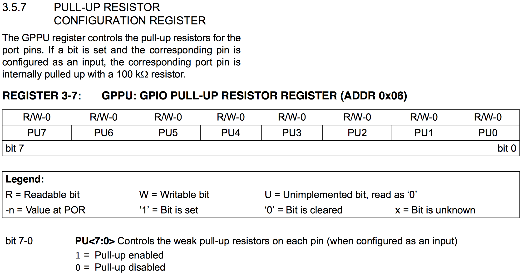
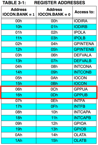
However, internal pull-ups are disabled by default. You need to enable them through configuration of registers GPPUA (address either 0x06 or 0x0C, see below) and GPPUB (address either 0x16 or 0x0D, see below) according to this pattern (from the datasheet):

Pull-up resistor configuration register

Note that the address of the GPPUA and GPPUB registers depends on whether you're using the MCP23017 in 8-bit or 16-bit mode (something you configure through IOCON.BANK). This table from the datasheet tells you which address should you use for each mode:

Register addresses

\$\endgroup\$
2
  • \$\begingroup\$ Thanks @EnricBlanco! I added a breadboard view on the question to show what I want to do (connect many tact switches to MCP2017, which is itself connected to a RPi). Do you think your answer will apply in this context ? (i.e. no extra resistors needed) \$\endgroup\$
    – Basj
    Commented Apr 4, 2017 at 9:42
  • 2
    \$\begingroup\$ Hard to say because that wiring diagram isn't actually a schematic and is very difficult to read. Counting pins in the MCP23017, it looks like you're connecting the switches to ground (Vss, pin 10). That's correct indeed, provided you enable the internal pull-ups by configuring GPPUA and GPPUB as required. The GPAx pins will be HIGH by default thanks to the internal pull-ups, and then you'll drive them LOW when pushing the button by connecting them to ground (Vss). It should work if everything else is OK (i.e. don't forget to add decoupling capacitors to the power lines of the MCP23017, etc.). \$\endgroup\$ Commented Apr 4, 2017 at 10:02

Your Answer

By clicking “Post Your Answer”, you agree to our terms of service and acknowledge you have read our privacy policy.

Not the answer you're looking for? Browse other questions tagged or ask your own question.