2
\$\begingroup\$

I have an ATMEGA324P controlling a dual motor driver circuit. I'm using the 16-bit Timer Counter 1 in Phase and Frequency Correct mode to create (2) PWM outputs using the ICR1 as the TOP value and the OCR1A and OCR1B to generate the PWM signals on the output pins. The problem persists the same on OCR1A and OCR1B so I have disabled OCR1A to simplify troubleshooting.

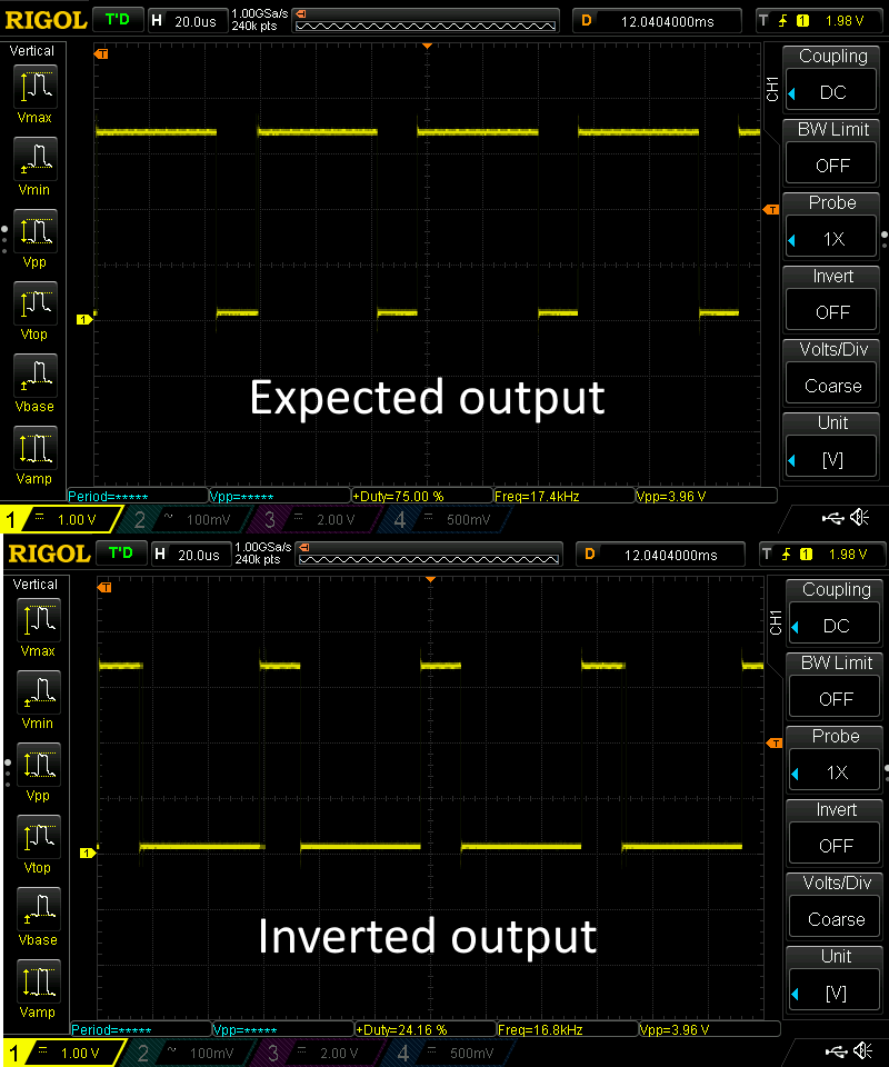
The problem I am experiencing is when any other interrupts on the system fires , such as UART or PCINT, the PWM duty cycle will invert. For example if the duty cycle is set to 75% it will invert to 25% and flop back and forth as other interrupts fire making the output extremely erratic. The scope shots below show the desired output on top and the inverted on bottom. I've been able to trigger this inversion by UART RX ISR, Pin change interrupt ISR, and Timer Counter 0 and 2 Compare A & B ISR's. For example sending a character to the UART will cause it to invert.

Scope Shot

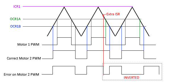
Everything seems to work in my code (below) except for this issue. I have tried a new circuit board and it exhibited the exact same behavior which suggests it's not a hardware problem. What I think might be happening is the OCR1B interrupt is somehow triggered when the other interrupt fires causing an extra OCR1B toggle of the output pin. Once this happens it keeps working as it should, toggling the pin but in an inverted state. This is illustrated in the timing diagram below.

enter image description here

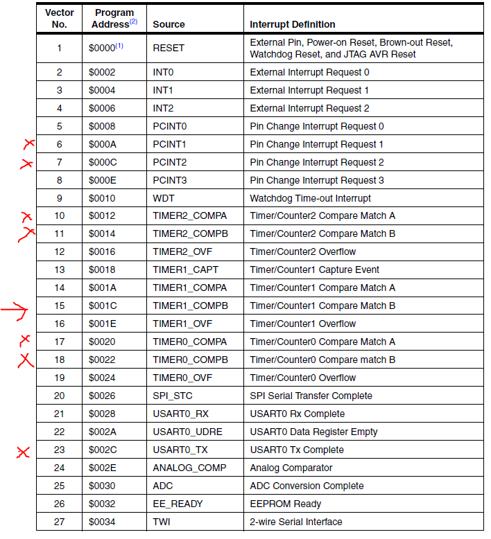
It's possible I have some error with my stack and the ISR address is being corrupted. The addresses I've tried are shown below with the X and the target address with the arrow. I appreciate any help.

enter image description here

#define SS_Hi()         PORTB |= _BV(4)
#define SS_Lo()         PORTB &= ~ _BV(4)
#define SS_IN()     (PINB&_BV(PINB4))


void init_TCNT1(void) {

    // setup timer counter 1

    // PWM, Phase Frequency Correct 8-bit. TOP = ICR1

    TCCR1A |= _BV(WGM11);
    TCCR1B |= _BV(WGM13);
    TCCR1B |= _BV(CS11); 

    ICR1 = 40;  

    TIMSK1 |= _BV(OCIE1A); 
//  TIMSK1 |= _BV(OCIE1B);

    OCR1A = 10; 
    OCR1B = 10;
    TCNT1 = 0; 

}

ISR(TIMER1_COMPA_vect) {

    if ((EnA_1() != 0) && (EnB_1() != 0)) { // only if both enable pins are high

    // if (PWM_PIN_1() == 0) PWMIN_1_Hi(); else PWMIN_1_Lo();

    }
    else PWMIN_1_Lo();
} // End Timer 1 Compare A ISR

ISR(TIMER1_COMPB_vect) {
// ISR For Motor 2
    if (SS_IN() == 0) SS_Hi(); else SS_Lo();
} // End Timer 1 Compare B ISR
\$\endgroup\$
5
  • 1
    \$\begingroup\$ Question: Are you manually toggling the output pins or are you using the OCRn outputs to automatically do PWM on those pins? It almost looks like you're doing it manually. \$\endgroup\$ Commented Apr 6, 2017 at 4:28
  • \$\begingroup\$ Manually. The actual PWM pin is hardwired to a driver IC so I moved it in code to an unused pin (slave select pin on PB4) for troubleshooting. \$\endgroup\$
    – Neelix
    Commented Apr 6, 2017 at 4:39
  • 2
    \$\begingroup\$ Do you see this issue even when doing it automatically? I've used PWM on the ATMega for dozens of applications and not had problems when its set up correctly (and automatic pwm won't care about the stack or any other activity (like UART interrupts) since the timer control registers are in a different memory space and everything is happening without CPU control). \$\endgroup\$ Commented Apr 6, 2017 at 4:43
  • \$\begingroup\$ So if a compare match interrupt is missed the signal will invert? \$\endgroup\$ Commented Apr 6, 2017 at 11:07
  • \$\begingroup\$ I tested it using the OCR1B pin on PD4 and it does not invert. \$\endgroup\$
    – Neelix
    Commented Apr 6, 2017 at 14:34

2 Answers 2

1
\$\begingroup\$

With the help of the comments and the below post I was able to determine the cause of the issue.

https://stackoverflow.com/questions/24128926/what-happens-when-an-isr-is-running-and-another-interrupt-happens

The cause of the problem is not an extra interrupt as I had originally thought it's that one is being missed because the global interrupts were disabled to handle another ISR. I was able to verify this by adding an sei(); instruction at the beginning of all the other ISR handlers and the inverting issue went away. Re-enabling global interrupts in every other ISR is not an ideal solution and causes more issues especially with the UART. The best solution would be to use the OCR1A/B pins on PD4 and PD5 however these pins are used for something else so that's not really an option. The solution I came up with is to use the Timer 1 Overflow interrupt to clear the output pin which fires on BOTTOM in Phase and Frequency PWM mode. So regardless if a toggle is missed when the counter is at the bottom the pin will be cleared and the error will only exist for a few cycles at most.

#define SS_Hi() PORTB |= _BV(4)
# define SS_Lo() PORTB &= ~_BV(4)
# define SS_IN()(PINB & _BV(PINB4))

void init_TCNT1(void) {
  // setup timer counter 1
  // PWM, Phase and Frequency Correct 8-bit. TOP = ICR1

  TCCR1A |= _BV(WGM11);
  TCCR1B |= _BV(WGM13);
  TCCR1B |= _BV(CS11);

  ICR1 = 40;

  TIMSK1 |= _BV(OCIE1A);
  TIMSK1 |= _BV(OCIE1B);
  TIMSK1 |= _BV(TOIE1);

  OCR1A = 10; //Set the top value
  OCR1B = 10; // Set the compare value 
  TCNT1 = 0; // intitilize the start value 

}

ISR(TIMER1_COMPA_vect) {

    if ((EnA_1() != 0) && (EnB_1() != 0))

  } // End Timer 1 Compare A ISR

ISR(TIMER1_COMPB_vect) {
    // ISR For Motor 2

    if (SS_IN() == 0) SS_Hi();
    else SS_Lo();

  } // End Timer 1 Compare B ISR
ISR(TIMER1_OVF_vect) {

  SS_Lo();
}
\$\endgroup\$
0
\$\begingroup\$

Since you are manually toggling the pins in the isr, you are exposed to rmw. So what you have experienced is possible.

Configure the COMx bits instead.

\$\endgroup\$
5
  • \$\begingroup\$ Unfortunately this is on a printed circuit board where the COMx pins go elsewhere. \$\endgroup\$
    – Neelix
    Commented Apr 6, 2017 at 15:51
  • \$\begingroup\$ I was talking about the COMx bits not pins. Like com1a1..0 or com1b1..0. Especially to out the ocr1x pins to own mode. \$\endgroup\$
    – dannyf
    Commented Apr 6, 2017 at 16:00
  • \$\begingroup\$ If those pins are used elsewhere, try pin flip instead, or shadow registers. \$\endgroup\$
    – dannyf
    Commented Apr 6, 2017 at 16:01
  • \$\begingroup\$ It is always bad practice to produce a pcb when you haven't nailed down your software. \$\endgroup\$
    – dannyf
    Commented Apr 6, 2017 at 16:02
  • \$\begingroup\$ I'm curious about shadowing the register, can you provide more detail on how to achieve this or a guide I can reference? \$\endgroup\$
    – Neelix
    Commented Apr 6, 2017 at 17:22

Your Answer

By clicking “Post Your Answer”, you agree to our terms of service and acknowledge you have read our privacy policy.

Not the answer you're looking for? Browse other questions tagged or ask your own question.