1
\$\begingroup\$

I have this little project that requires exact clock so I'm using 32768 Hz quartz on RB6 & RB7 on my PIC16F628. Both pins are grounded using 33 pF capacitors.

My code that configures the timer1 is as follows (HI-TECH C compiler):

TRISA = 0b11100011; //x3F;      // bit=0 - output; bit=1 - input
TRISB = 0b11110000; //x3F;      // bit=0 - output; bit=1 - input
nRBPU = 1; //affects inputs only
TMR1ON = 0;     // Disable Timer 1
T1CKPS1 = T1CKPS0 = 0;   // 1:1 Prescale value
T1OSCEN = 1; //start tmr1 oscillator
TMR1CS = 1;  //0: internal clock; 1: wait external clock
nT1SYNC = 0; //sync by external clock
TMR1 = 0x8000;
PEIE = 1;
TMR1IE = 1;
ei(); //sets GIE
//T1CON = 0b00001111;
TMR1ON = 1;     // Enable Timer 1

The config bits:

__CONFIG(WDTE_OFF & MCLRE_ON & PWRTE_ON & BOREN_OFF & LVP_ON & FOSC_INTOSCIO & CP_OFF & CPD_OFF);

The problem - it never runs. I have an LED in the ISR that should be lighted up. Also I used an oscilloscope to investigate. Changed the capacitors. Tried another crystal. Tried all possible approaches. Nothing helped.

\$\endgroup\$
5
  • 2
    \$\begingroup\$ Please show your configuration bits. \$\endgroup\$ Commented Apr 11, 2012 at 18:23
  • 2
    \$\begingroup\$ You used the Internal Oscillator, but you should have used the Low Power Oscillator in the Configuration bits \$\endgroup\$
    – m.Alin
    Commented Apr 11, 2012 at 19:20
  • 1
    \$\begingroup\$ @m.Alin, my guess is you mean "FOSC_LP" mode /which demands crystal on ra6 and ra7/ but isn't this mode about the chip's main oscillator? My goal is to use the internal RC oscillator as a chip clock and timer1 oscillator as a timer1 clock. \$\endgroup\$
    – Nedko
    Commented Apr 11, 2012 at 21:33
  • \$\begingroup\$ @Nedko So is there a reason why you're not using the 32768 Hz quartz as your main oscillator? \$\endgroup\$
    – m.Alin
    Commented Apr 12, 2012 at 10:07
  • \$\begingroup\$ I wish to have more processing power - with 4mhz the clock is 1 uS; with 32768 KHz - it's 122 uS. Well it seems that I will end up using 32KHz or 4MHz as the main oscillator. \$\endgroup\$
    – Nedko
    Commented Apr 12, 2012 at 10:38

1 Answer 1

1
\$\begingroup\$

The directive FOSC_INTOSCIO means that the part is using its internal oscillator, and the lines normally used for the crystal are set as I/O lines. That's why your crystal isn't oscillating.

This device has an internal oscillator frequency of approximately 4MHz, so it's quite possible that your ISR is executing faster than your eye can perceive the LED flashing.

You will want to use something like LP_OSC instead of FOSC_INTOSCIO (I don't have that exact header file, so I cannot tell you which exact one to use).


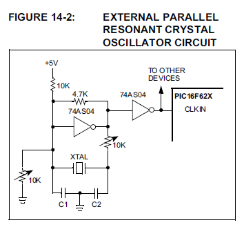
Further to the comment below: according to the datasheet, the choices for the timer clock source are: an external clock from RB6 or the internal oscillator / 4. What this means is that you can use the internal 4 MHz oscillator for the main clock, and bring a clock signal to RB6 for the timer. However, since you're not using the built-in oscillator hardware, you'll have to externally generate a clock from the crystal and apply it to RB6.

Luckily Microchip explains how in the datasheet:

Parallel crystal circuit

Serial crystal circuit

\$\endgroup\$
1
  • \$\begingroup\$ Madmanguruman, thank you for your answer. As long as I see the FOSC_LP mode actually expects a crystal connected to RA6 and RA7 and I have none there. My goal is to use the internal RC oscillator as a chip clock and timer1 oscillator as a timer1 clock, but the timer1 oscillator stubbornly does not tick. An oscilloscope also does not show activity on the RTC crystal. By this time I can't find any evidence that running timer1 oscillator is a tricky one, so I begin to wonder isn't my chip defected? \$\endgroup\$
    – Nedko
    Commented Apr 11, 2012 at 21:53

Your Answer

By clicking “Post Your Answer”, you agree to our terms of service and acknowledge you have read our privacy policy.

Not the answer you're looking for? Browse other questions tagged or ask your own question.