1
\$\begingroup\$

For a project of mine I need to step down 12V to 5V and also 5V to 3.3V. However, I don't have any heat sinks for my voltage regulators. From the equation below, if I reduce the difference between the input voltage and output voltage of the regulator, I can reduce the power dissipation.

If I use a voltage divider to step down 12V to 6V and then use the 6V as the input of the regulator, would that then decrease the heat significantly, or does the heat still generated but at the divider?

Sorry for the noob question, it is my first time messing with power supply other than the 5V.

EDIT: forgot equation for reference

Power = (Vin - Vout) x Iout

\$\endgroup\$
1
  • 1
    \$\begingroup\$ Aside from the usual objections to using a resistive voltage divider (most classwork will have you attempt this quite early in order to get the point across about how bad the idea usually is -- there are exceptions to everything, of course), can you disclose what you expect as the current loading for the two new voltage rails? Do you have any idea? (Heat sinks can be cobbled up from random stuff around the home, by the way.) And no, you can't reduce the power dissipation using passive regulator means. 12 V times whatever current is needed will be the power. You only control where. \$\endgroup\$
    – jonk
    Commented Apr 8, 2017 at 17:15

5 Answers 5

2
\$\begingroup\$

Your idea of using a voltage divider is not viable at all. You have to dissipate the power in a linear regulation system somewhere, and typically would do this in the regulator.
....but you could add a series resistor to drop the voltage at your target load current ...this would spread the dissipation between the regulator and the resistor. You still have exactly the same power dissipation however, and you have to make sure you don't exceed the current limit you used to select the resistor.

You could also use a Zener diode or set up a pass transistor with a smaller resistor to allow you to spread the dissipation between multiple devices. This can work, but again you are simply spreading the power dissipation between devices instead of providing a heatsink for the regulator.

\$\endgroup\$
2
\$\begingroup\$

Voltage dropping through a resistor, or a transistor, from 12V to 5V, always delivers heat as the equation above expresses. There is no exception for parts-added circuitry that only puts in more resistors, but there IS a less heat-producing scheme, using switchmode regulation and inductors. If your plan was to use, for instance, a LM7805 regulator without a heatsink, suitable pin-compatible parts are available DC/DC converter that are more efficient than that equation (and presumably don't need a heatsink).

Also possible, use a heatsink. It can be ANYTHING, a dab of glue and a big washer will do SOME heat dissipation. There's an equation for the heat generated, and there's more equations for how the package temperature rises, with and without heatsinking. So, you can calculate. The temperature of the regulator can be measured under load, so you can verify adequate heat shedding to keep the regulator in its operating temperature range by testing with your load, while watching the thermometer.

Either by calculation or by experimentation, or by using different parts, three paths forward are open.

\$\endgroup\$
2
\$\begingroup\$

First of all, it is good to spread out heat dissipation across multiple components. That's why for sure you should use some passive components for lowering voltage before your regulator. Lets take the further example: Regulator on 3.3
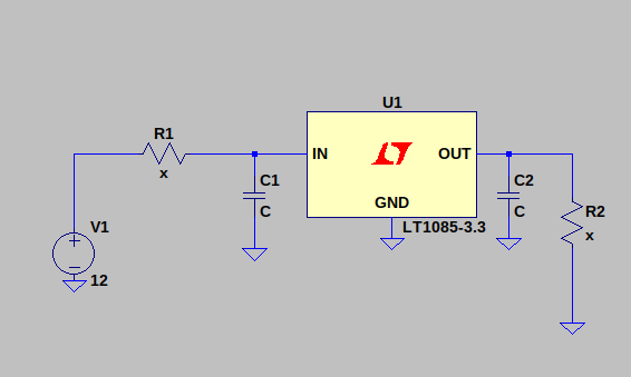
First of all, you should know how to treat voltage regulator from aspect of power consumption. Note that your regulator is taking some of your input current, so just for our current perspective, we can take next model for voltage regulator: Simplified model of regulator
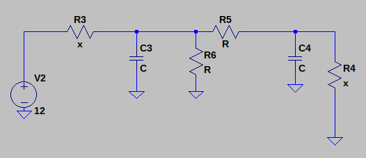
So, current for R1 and R5, wont be the same. One part of R1 current will go through the R6 (consumption of regulator). You can find this current in datasheet of the regulator you are using.

Now, if you know that you want to have 3.3V on output (Vout) of particular regulator, that means that next equation will do:

R2*Iout = 3.3V

On the other side of regulator, you want to lower your Vin voltage which will be:

Vin = V1 - R1*I1

Note also relations of current, where I1 = Iout + Iu, where Iu is load current of regulator (according to simplified model, current through R6 resistor).

Now, when you know V1, you need to decide what should your Iout be (consult your datasheet for available range). For example, you want it to be 500mA:

R2*500mA = 3.3
V1 - R1*(500mA+Iu) = Vin

You would like Vin (in this case) to be something between 4 and 5V, so from two upper equations you can choose your R1 resistor, presumably you know what your load (R2) is.

@dim: Is this more suitable then my previous answer?

\$\endgroup\$
2
  • \$\begingroup\$ So, how much current do you expect a voltage divider to output without significant voltage drop ? \$\endgroup\$
    – Long Pham
    Commented Jun 12, 2018 at 13:02
  • \$\begingroup\$ @Long Pham Answer corrected with usage of one serial resistor. \$\endgroup\$ Commented Jun 13, 2018 at 5:57
0
\$\begingroup\$

Your voltage divider will consume current and if you try to put high value resistor to avoid this problem, your output voltage of 6V will decrease if you take too much current in output to supply the regulator. So the best solution would be the first, with low value resistor, but you will loose too much power in the voltage divider because of the current.

\$\endgroup\$
0
\$\begingroup\$

Like the above answers state, there's no getting around the physics of the problem: The amount of power you dissipate as heat from regulating the voltage is your current requirements times your voltage drop. If this causes the regulator to reach a higher temperature than you are comfortable with or beyond the operating specifications of your part, then you can either heat sink your regulator, or cascade regulators, which in essence is just distributing the power dissipation onto multiple devices.

There are usually equations in good data sheets to help you calculate a) if you need a heatsink, and b) The thermal resistance of the heat sink you require, given the maximum temperature of the part, and the ambient air temperature.

\$\endgroup\$

Your Answer

By clicking “Post Your Answer”, you agree to our terms of service and acknowledge you have read our privacy policy.

Not the answer you're looking for? Browse other questions tagged or ask your own question.