1
\$\begingroup\$

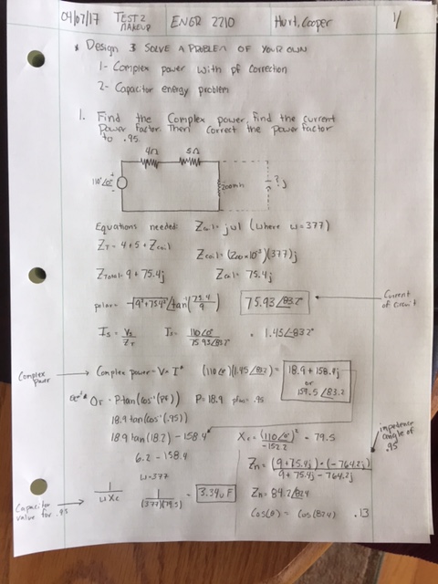
I was responsible for making up my own question and providing the answer to the problem. I was just wondering if someone could check my work, I would go to my schools tutoring thing but they are closed over the weekend.

I believe I have all the right work just have some weird numbers.

The first to are in series so simplifies to 9ohms in series with the 200mj inductor
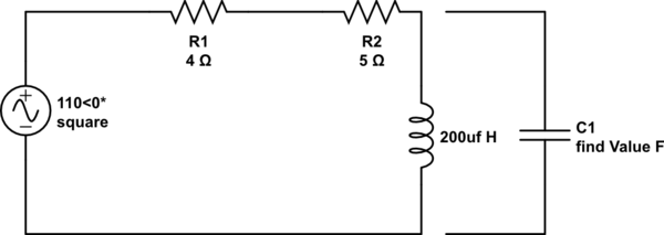
schematic

simulate this circuit – Schematic created using CircuitLab

I then want them to have them correct the power factor to .95, then calculate the new impedance angle of .95.

Let me know if you see any mistakes. I can't get it to stay upright to read, so if it doesn't work here is uploaded version of it:

https://i.sstatic.net/IdUeN.jpg

enter image description here

Believe the power factor is: 18.9+158.9j or 159<-83.2*

The to correct the power factor to .95 we need a 3.39uF capacitor.

\$\endgroup\$
6
  • \$\begingroup\$ Sorry dude, try writing down your question (in the space allowed) and not posting a picture that is impossible to read. Then you should state (in the question and not in the picture) what answers you believe to be weird and why you think they are weird. Also what the hell does "200mj induct or" mean? Were you rushing maybe? There is a circuit editor you can use when editing your question. \$\endgroup\$
    – Andy aka
    Commented Apr 8, 2017 at 18:36
  • \$\begingroup\$ Ok edited and put what I thought the answers were. \$\endgroup\$
    – noreturn
    Commented Apr 8, 2017 at 18:52
  • \$\begingroup\$ Now your inductor is labelled 200uf H. In the text you refer to a 200mj inductor. Your source has the word "square" next to it, is it sinusoidal? Please clean up your units. \$\endgroup\$
    – John D
    Commented Apr 8, 2017 at 19:28
  • \$\begingroup\$ Just make ZL=Zc at 60Hz for PF=1 (big C) \$\endgroup\$
    – D.A.S.
    Commented Apr 8, 2017 at 20:06
  • \$\begingroup\$ We never learned about a sinusoidal. I labeled it 200mj. \$\endgroup\$
    – noreturn
    Commented Apr 8, 2017 at 20:22

1 Answer 1

0
\$\begingroup\$

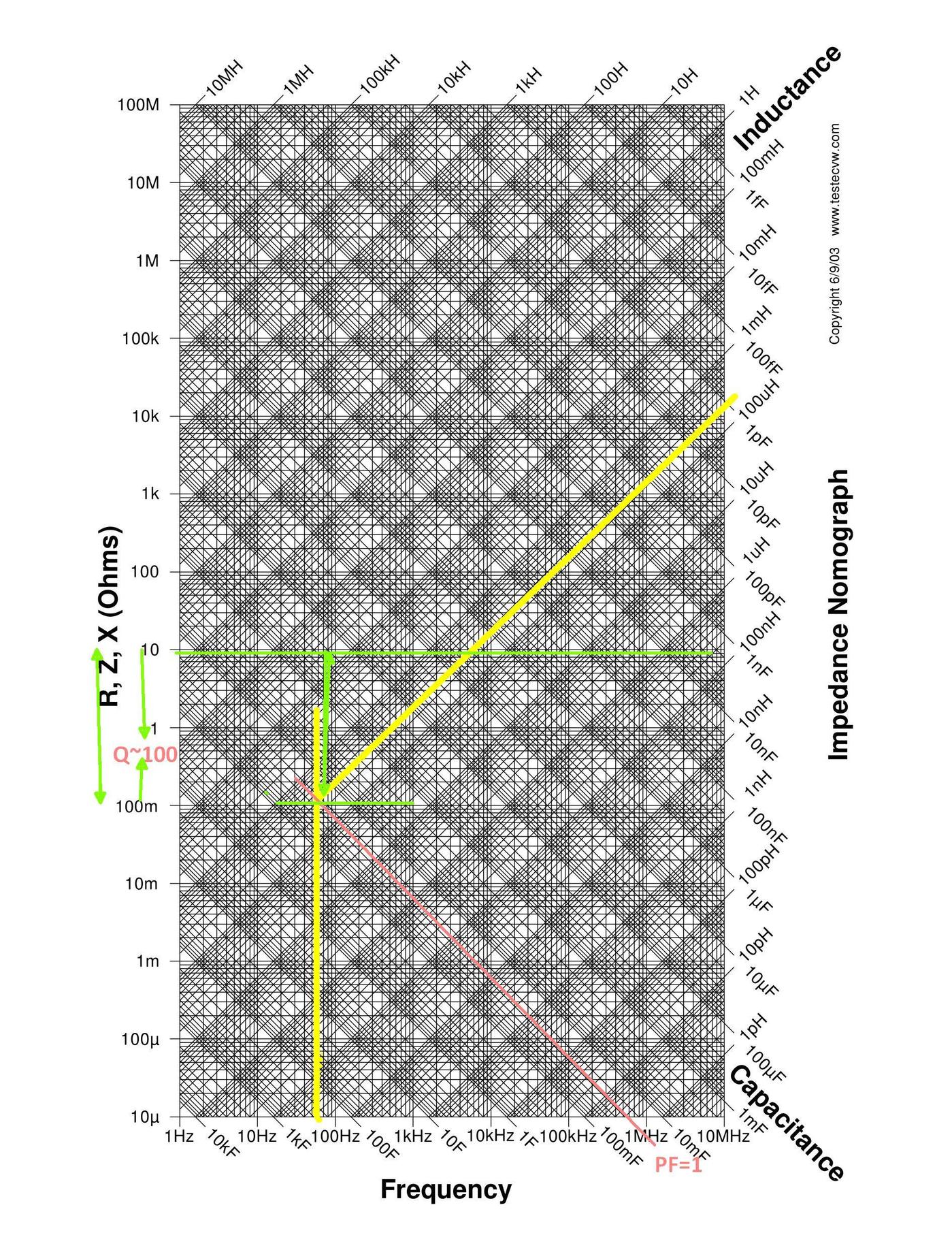
Check your values and look for PF=1 at the intersection of this parallel Resonant Circuit if 200uH then the Q=100 , if 200mH then more normal Q<1 and 35uF Cap.

enter image description here

Consider PF=1 with "conjugate" impedance then check power W/VAR ratio for PF =0.95 and compare for quick check.

\$\endgroup\$

Your Answer

By clicking “Post Your Answer”, you agree to our terms of service and acknowledge you have read our privacy policy.

Not the answer you're looking for? Browse other questions tagged or ask your own question.