0
\$\begingroup\$

I just wanted to ask if this power switching circuit is well done. I used an opamp and a MOSFET to select between two different power supplies connected at once. This circuit would select the highest input voltage, in this case, 12V Here's a pic: POWER SELECTOR
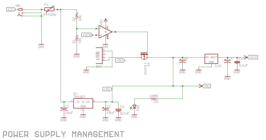

Following Tony and Jack's steps, I tried to make some changes and improve the circuit, but I'm not sure it's 100% functional, well, I'm a noob at electronics :)

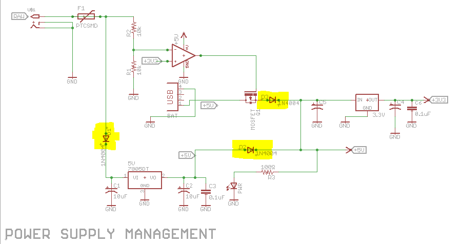
CIRCUIT IMPROVED

\$\endgroup\$
7
  • 1
    \$\begingroup\$ Don't forget about the FETs body diode. It's going to conduct even if the FET is off. \$\endgroup\$
    – Wesley Lee
    Commented Apr 16, 2017 at 15:38
  • \$\begingroup\$ @WesleyLee So what type of MOSFET should I use, N-channel or P-channel? \$\endgroup\$ Commented Apr 16, 2017 at 15:44
  • \$\begingroup\$ The type doesn't matter, although it will be easier with a P-FET. Some power selection circuits actually use it as a feature, to turn the FET on slowly first. I'm just reminding you of it. \$\endgroup\$
    – Wesley Lee
    Commented Apr 16, 2017 at 15:49
  • \$\begingroup\$ It looks like the op-amp is powered by 5 V, but you could expect 6 V applied to the inverting input. Maybe okay with the 10 kOhm limiting the current, but probably not best practice. \$\endgroup\$
    – The Photon
    Commented Apr 16, 2017 at 17:23
  • \$\begingroup\$ D2 and D3 are completely unnecessary in your modified schematic. If you did put them in, they'd have to be Schottky diodes (with very low Vf) and they make Q1 and the op-amp unnecessary (under any scenario). ....If you intend to use both 5v and 3V3 to power circuit elements in your design, then one assumes you want 5 V and not 4.75 V (what you'd get if you insert those diodes). There is no protection you need to put in place for the 3V3 LDO. \$\endgroup\$ Commented Apr 16, 2017 at 18:19

2 Answers 2

1
\$\begingroup\$

I'd suggest you are way overthinking the need for isolating the power sources.

As a note: Your linear regulator seems to be a 7818DT ...that is an 18 Volt regulator. Did you actually mean to use a 7805 regulator?

  1. Assuming that the linear regulator is in fact a 5 Volt 78xx version regulator, you need to provide backpower protection. Put a diode between the Fuse and the input capacitor to the regulator. Anode to Fuse, Cathode to cap/regulator.

  2. Assuming your USB power input is a USB output Walwart you don't need Q1 to isolate it. Just as you don't have a diode in the output of the 5 volt regulator, it makes no sense in the USB line. If the 5 V provided by one regulator is above that of the other, the respective (other) regulator will simply shut down.
    If the USB power connection is from a computer/tablet/etc then they will either current share, or the upstream provider will shutdown as per standard.
    Either way you achieve nothing but increased complexity by adding Q1 and the op-amp.

If you really really really want to have isolation, then simply add a Schottky diode in series with the USB power input.

\$\endgroup\$
0
\$\begingroup\$

ok but depending on shutdown speed at input reverse current can damage LDO's so reverse diode protection is advised.

Ensure VI drop on LDO with Rth_ja does not exceed 50'C at rated load.

\$\endgroup\$
2
  • \$\begingroup\$ where should I add the reverse protection diodes? \$\endgroup\$ Commented Apr 16, 2017 at 15:47
  • \$\begingroup\$ across IO of LDO, consult datasheet for examples. \$\endgroup\$
    – D.A.S.
    Commented Apr 16, 2017 at 16:00

Your Answer

By clicking “Post Your Answer”, you agree to our terms of service and acknowledge you have read our privacy policy.

Not the answer you're looking for? Browse other questions tagged or ask your own question.