There is a special "problem" with this device (and presumably with many LASERS) compared to many other electronic components. Whereas we usually cool a device
To limit Tj (junction temperature) to a value that allows reliability and long life. Typically Tjmax may be in the 120-150C range BUT Tj operating is often kept much lower than this. This is to some extent changing - eg modern LEDs are now often specified to operate at 85C and some at 105 C and Cree lighting LED spec sheets give data for 105C operation and do not give specs at low temperatures.
To limit Tc (case temperature) to a temperature that is not "offensively high" even though electrically it may not matter. eg Tc above 50 C means the heat sink will burn fingers and Tc > 100C means the heatsink will boil water and cook eggs.
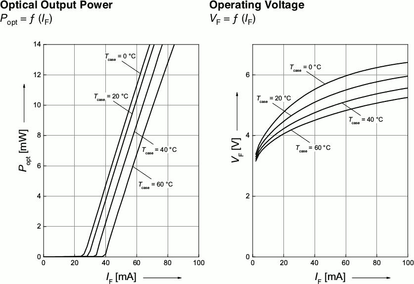
Whereas, in this case the efficiency of the device drops very significantly for increasing Tj. At a constant 60 mA you may get about 10.25 mW optical power out at Tc = 20C (Tj = say 30-45C) but only about 60% of that at Tc = 60C. As Tj and Tc rise power out drops, you need more power in to compensate, temperature rises further and efficiency drop further and you end up with VERY high Tc, low optical output and unacceptable efficiency. (Marcus covers that partially with his comment on the control loop.)
__________________________
Using the Osram PLT5 510 data sheet that Marcus cites.
Page 2 gives condition for 10 mW output at 10 mW optical.
At an unrealistic Tcase = 25C the specifications are:
Vf = 5.5V typical, 7.0V max.
Idc = 60 mA typical, 100 mA max.
Internal thermal resistance of the device Tjc = 34 K/W
Neglecting the small amount of "cooling" due to radiant LASER energy, the heat power to be dissipated = V x I = 5.5V x 60 mA = 330 mW typical and 7V x 100 mA = 700 mW max.
Internal IC temperature rise = Tjc x power = 34 x 0.33 to 0.7W = 11 C to 24C rise junction to case.
Allowable Tj operating = 120 C (page 1) BUT allowable Tcase_operating = 60C.
These two specs plus the expected temperature rise internally "do not make sense", but we'll see what can be managed.
Looking at the optical power output curve cited by Marcus we can see that at constant 60 mA, output at Tc (Tcase) =
Tc mW-out
0 11.5
20 10.25
40 8.5
60 6.5
ie power drop per degree C increases with increasing temperature and at 90C case that you report, at 60 mA you'd expect Pout of perhaps 3+ mW - about twice what you report at your unstated V_LASER and I_LASER.
Essentially, you are baking it to death.
As Marcus says, it MUST be cooler.
To get it to TCase = 20C and worst case input of 24 C rise Tjc at 0.7 W you'd need a heat sink between ambient and case of thermal resistance
Rac = (Tc-Ta) / Power
(as Trise = power x resistance so resistance = delta_T/Power.)
Unless you are working in an unheated lab in higher lattitudes in winter, to get a Ta that works in practice you need perhaps a Peltier cooler or some other source of coolth in the say 0-10C range.
eg at Ta = 10C, Rac = (20-10)/0.7W ~= 14 C/W heatsink, and at Ta = 0C (eg ice + water) you need a 28 C/W heatsink.
So eg maintaining a bath of meltwater around a block of water ice as your cold source allows a relatively modest heatsinnk and passive cooling or an even more modest one and a small fan.
IF your Ta / air temperature is not over say 20C you could use vigorous air blowing and as useful a heatsink as you can manage and probably maintain Tc in the 25-30C range. This will decrease your power output by about 10 - 15% compared to 20C at constant current - but if you can test select diodes by hand the spec sheet suggests that a better than 2 times improvement in output may be possible.
SO:
Select for a good output diode.
Heatsink as well as possible
Air blow heatsink.
Use as cool a source as possible - 0-10C ideal. 20C maybe bearable.
This is, not too too surprisingly, similar to what Marcus concludes, but may give additional insight into why it works. Or not :-).


