2
\$\begingroup\$

I can sweep the frequency in time by using modulate, but I couldn't find any example on creating a varying duty cycle or a duty cycle is swept from zero to 100% at a given frequency f in a time interval.

Is there a way/workaround to sweep duty cycle over time in LTspice?

Edit:

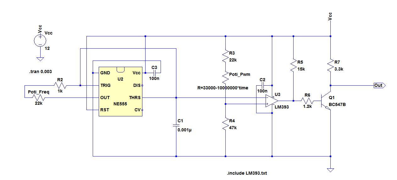
I have the following timer circuit which can do that. But that wasn't I was looking for, since this type of solution slows down the simulation a lot. I was wondering is there a fast way to do that with a single special function or SPICE command.

enter image description here

Please left click on the below plot to enlarge and be able to see the duty cycle variation:

enter image description here

\$\endgroup\$
2
  • 1
    \$\begingroup\$ For clarification, can you add an example of the proposed waveform? And I assume you mean a voltage source? \$\endgroup\$
    – PlasmaHH
    Commented Apr 21, 2017 at 11:17
  • \$\begingroup\$ I added an example \$\endgroup\$
    – user16307
    Commented Apr 21, 2017 at 11:48

6 Answers 6

3
\$\begingroup\$

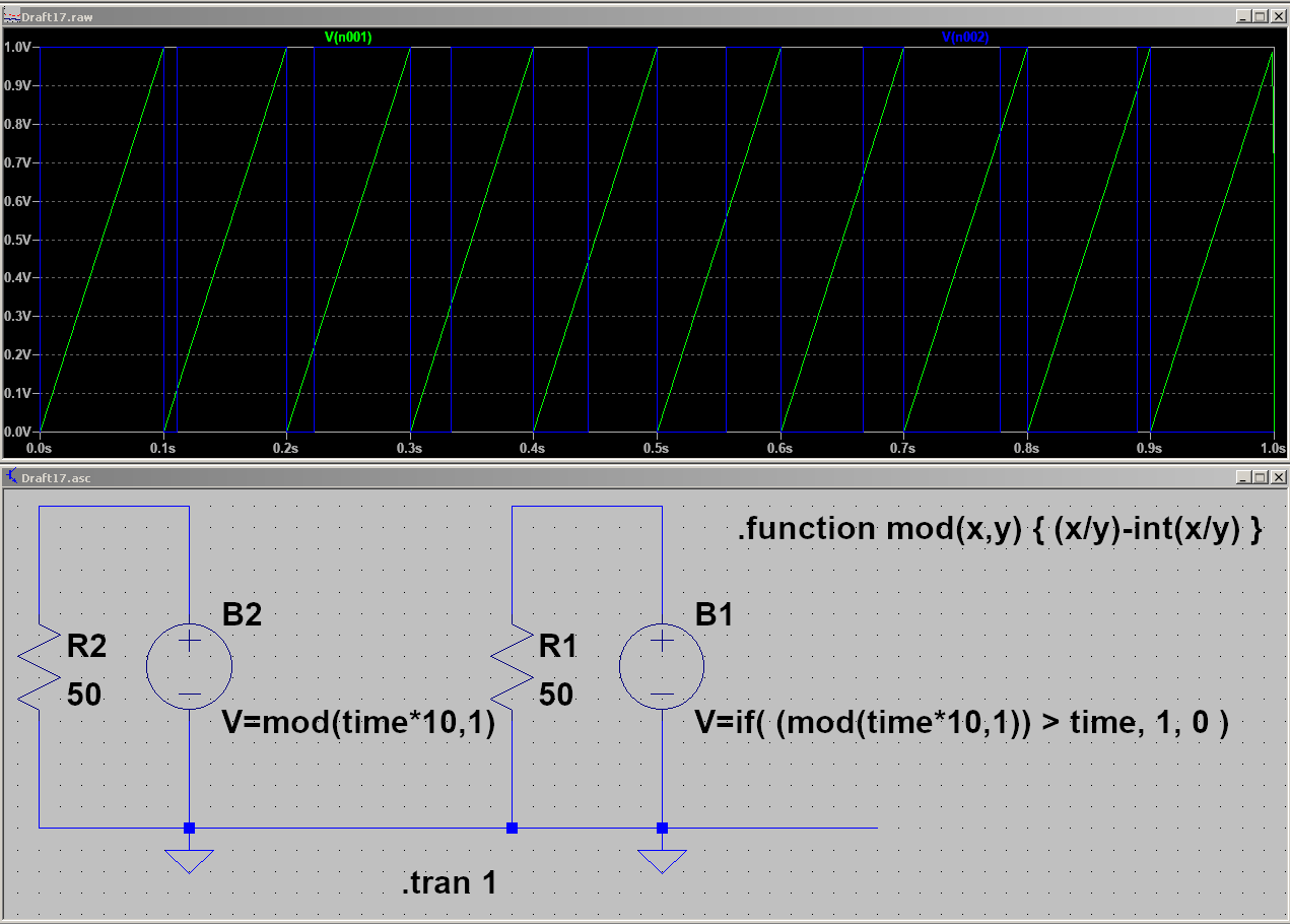
I am not quite sure if this is what you really want, but lets try anyways. First we create a sawtooth ramp with a certain frequency by using our own defined modulo function with the time (green trace):

.function mod(x,y) { (x/y)-int(x/y) }

Then we use the actual time and the if function as a cutoff point for creating a square wave with an arbitrary voltage source:

V=if( (mod(time*10,1)) > time, 1, 0 )

enter image description here

This should give you a good starting point to tinker around and adapt to your needs.

\$\endgroup\$
1
  • \$\begingroup\$ After creating my own solution I understood yours as well... Because it is basically the same thing. \$\endgroup\$
    – Arsenal
    Commented Apr 21, 2017 at 14:38
3
\$\begingroup\$

The best way to do it, both simulation- and efficient-wise, is with A-devices:

pwm

This allows you to not only vary the control and carrier separately, however you wish, but you also have access to vt (threshold) and vh (hysteresis) for the comparator, you have temporal aids like Rout/Cout, or tau, or trise/tfall (pick one option out of the three), that also help convergence, you can set vhigh/vlow to whatever levels you wish, and it will simulate as fast as it can without any problems. Convergence is guaranteed.

For the signals, I recommend using the basic voltage source, unless they are generated elsewhere in the circuit, dynamically.


I just realized @Bimpelrekkie proposed about the same thing, but, in my defense, I explicitly pointed out the elements to use.

\$\endgroup\$
2
\$\begingroup\$

I'm not an LTspice user so I do not know if the required ideal components are available in LTspice.

But assuming they are you can build your own system for this, like so:

schematic

simulate this circuit – Schematic created using CircuitLab

Basically the circuit compares a (fast) 1 MHz triangle wave with a (slow) ramp of 100 ms. When slow is 0.5 V the comparator's output will have a 50% duty cycle as the triangle wave is below 0.5 V half of the time and above the other half of the time.

You can make an ideal comparator (when it is not available) by using an VCVS (Voltage Controlled Voltage Source) with a gain of for example 1000 and limited output values, for example 0 and 1 V.

\$\endgroup\$
3
  • \$\begingroup\$ I have timer circuit(see my edit) but Im not looking for a circuit; I was looking for a fast function like modulate for freq. sweeps. I want to use duty cycle sweep as an in put to another circuit. \$\endgroup\$
    – user16307
    Commented Apr 21, 2017 at 11:47
  • 1
    \$\begingroup\$ Hmm, then you didn't really ask what you wanted to ask now did you ? Since PlasmaHH's answer provides a similar solution as my answer, I conclude it's not that I didn't understand properly. As far as I know there is no single command to generate what you want. But my and PlasmaHH's solutions will for sure run a lot faster than your NE555 based circuit for sure. If the NE555's model is a complicated one it will slow things down a lot. \$\endgroup\$ Commented Apr 21, 2017 at 13:05
  • \$\begingroup\$ Choose (Schmitt) A-devices whenever possible over anything switching in nature. Their behaviour is far better and they also allow for some fine-grain control (vt/vh, td, tau/Cout,Rout/trise,tfall, ...). \$\endgroup\$ Commented Apr 22, 2017 at 5:25
2
\$\begingroup\$

This is not a fully perfected answer, but should give you a good starting point (I hope)

What I tried is using a arbitrary behavioral voltage source.

This is my netlist:

B1 NC_01 0 V=if((time/{period})-int(time/{period})<time*{ontime},{Von},{Voff})
.param period 1
.param ontime=1/100
.param Von 3
.param Voff 0
.tran 100
.backanno
.end

And the screenshot with the result: Varying pulse width with time with a simple voltage source


Break down of the behavioral voltage source function:

First note that behavioral voltage sources have access to the simulation time using time as parameter to functions. This is not available in .param statements.

First we need some function which allows us to allow a PWM function based on the current time. For this the if(x,y,z) construct is helpful. But a simple if(time<{ontime},3,0) will not produce a recurring signal but only a pulse at the beginning.

This is where the next constructs comes in: (time/{period})-int(time/{period}) This is basically just time modulus period, but there is no modulus operator, so I have to go down the route to subtract the integer part of time divided by period from the division of time and period. Duh.

Then you have to vary the ontime with regards to time. In this example I simply used the time with a factor of 1/100. ...<time*{ontime} Well ontime is not the best name for that parameter probably - it's more like a scaling factor.

\$\endgroup\$
1
\$\begingroup\$

I did it with a behavioural voltage source. Result is the same than using comparator, the modifying of the duty cycle is done by V2: PWM using BV and comparator

Here is the .asc code:

    Version 4
SHEET 1 880 680
WIRE 32 144 -48 144
WIRE 80 144 32 144
WIRE 272 144 144 144
WIRE 48 176 32 176
WIRE 80 176 48 176
FLAG 32 256 0
FLAG -48 224 0
FLAG 48 176 t1
FLAG 32 144 t2
FLAG 352 224 0
FLAG 352 144 u2
FLAG 272 144 u1
SYMBOL Digital\\diffschmitt 80 96 R0
WINDOW 3 8 32 Left 2
SYMATTR InstName A1
SYMATTR Value vt=0 vh=0 vhigh=3.3
SYMBOL voltage 32 160 R0
WINDOW 3 24 96 Left 1
WINDOW 123 0 0 Left 0
WINDOW 39 0 0 Left 0
SYMATTR InstName V1
SYMATTR Value PULSE(0 3.3 1p {0.5/freq} {0.5/freq} 1p {1./freq})
SYMBOL voltage -48 128 R0
WINDOW 3 24 96 Left 1
WINDOW 123 0 0 Left 0
WINDOW 39 0 0 Left 0
SYMATTR InstName V2
SYMATTR Value SINE(01.65 1.65 {freq2})
SYMBOL bv 352 128 R0
SYMATTR InstName B1
SYMATTR Value V=if(V(t2)>V(t1),3.3,0)
TEXT 296 64 Left 2 !.param freq=2khz freq2=freq/20
TEXT 16 72 Left 2 !.tran {25/freq}
TEXT -72 280 Left 1 !.OPTIONS METHOD=GEAR ABSTOL=1e-6 CHGTOL=1e-12 GMIN=1e-9 ITL1=1000 ITL2=1000 ITL4=1000 ITL6=1000 RELTOL= 0.001 VNTOL=1e-3 NOOPITER
\$\endgroup\$
0
\$\begingroup\$

Here is a swept sinewave using a B signal source in LTspice. The value of f and the voltage v(a) determines the frequency at any point in time.

\$\endgroup\$
1
  • 1
    \$\begingroup\$ Welcome to EE.SE! This is close, but OP asked about duty cycle. Can you modify your answer slightly to reflect this? \$\endgroup\$
    – winny
    Commented Jan 31, 2019 at 13:15

Your Answer

By clicking “Post Your Answer”, you agree to our terms of service and acknowledge you have read our privacy policy.

Not the answer you're looking for? Browse other questions tagged or ask your own question.