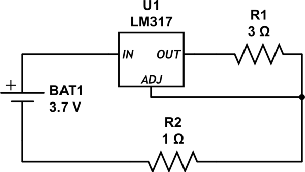
The LM317 needs a minimum of about 3v input to output. I haven't tested this but spec is :
VI – VO = 3 V to 40 V (from www.ti.com/lit/ds/symlink/lm317.pdf)
so the regulator is pretty certainly dropping out of regulation, given that the fully charged battery voltage is 4.2v and there is 1.2v dropped across the 3 ohm resistor.
You could use a low dropout regulator e.g. LD1117ADT12TR, which is a D-pak device that should work down to about 2.5V (in-out dropout 1.1v), download datasheet at:
www.st.com/resource/en/datasheet/ld1117a.pdf
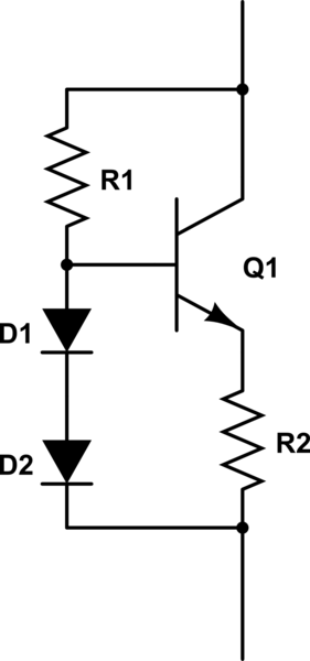
Regulation is not all that critical in this application, so you could probably use a reasonably high gain power transistor (not a darlington) and a couple of diodes (or 1 LED) as the regulator. You may have to adjust the resistors experimentally, depending on transistor gain, and the base-emitter junction and diode forward voltages.
R1 just has to be able to turn on transistor at low batt voltage (this current appears at the emitter) so for 400mA in the collector, the max R1 value will be a little less than $$ R_1 = \frac {(V_{BattLow} - V_{diodes})*transistor gain}{0.4} $$
R1 should be kept as high as poss without losing regulation at low batt. It needs to supply the transistor base current plus some to turn on the diodes enough to have a stable voltage across them.
It has more voltage across it at full batt voltage, so more current then flows through it. The extra current flows through the diodes, which hopefully hardly affects the voltage across them if they are already conducting well. Note that the voltage across R1 will be less if there is an additional voltage drop e.g. the 1 ohm series resistor (R2 in your circuit).
R2 sets the current limit. Use a resistor with enough power rating to run cool. $$R_2 = \frac {(V_{diodes} - V_{be})}{I_{lim}}$$
Diodes could be replaced with a suitable LED.
I'll expand on this a bit. P-N junctions (e.g. base-emitter, diode) have a fairly constant forward bias voltage of around 0.5 - 0.7v for silicon (reasonably independent of forward current once they are fully conducting). Most multimeters can measure this. Check the voltage vs. current curves on some data sheets for examples. Measure the ones you have at different currents.
For the purpose of this discussion I'll use 0.7v.
(Incidentally if you need to identify the leads of an unknown transistor, the base-collector junction is also like a diode, and generally has a slightly lower forward voltage than the base-emitter, measured at the same current).
The idea is that the transistor base-emitter junction (a FET won't work here) has 0.7v across it, the diodes also have 0.7v across them so 2 in series gives about 1.4v. (1N4007s should work ok if they are biased on with enough current through R1).
This means the base is at a constant 1.4v above the bottom of R2 and the emitter is at 1 base-emitter drop less than this (1.4-0.7 = 0.7v) so R2 has a fairly constant 0.7v across it and therefore a constant current through it. This is most of the current passed by the circuit.
A much smaller current flows through the diodes, just to forward bias them into their constant voltage state, which adds to the current passed by the circuit but is usually small enough not to matter.
The higher the transistor gain the better it compensates for changes in applied voltage and the higher you can make R1. A gain of >50 would be good (e.g. BD639).
Most LEDs also have a reasonably constant forward bias voltage (roughly related to colour) of between about 1.7 to 3.5v (I've seen voltages outside this range). To check the on-voltage, use a resistor in series with a LED (or diode), adjust the voltage applied as you measure the current through it and voltage across it. Plot the results if you want to see the curve. Find the minimum current needed to get a fairly stable voltage as the current changes. You want a low on-voltage (< 2v, infra red or red have the lowest) so that you don't run out of head-room. Note that some LEDs are designed to run directly from a battery and do not regulate V in this way.
If you can find a LED with a fairly stable and low on-voltage it could be used in place of the diodes. The brightness might even give you an idea of the state of charge. I have a feeling a LED on-voltage varies a bit more with current than a couple of diodes but I'm not sure. It might work ok.
Yes, good idea to use a variable power supply for testing the circuit between 4.2 and 3V. Ideally it should still be regulating well at the lowest voltage, which means you should probably leave out the 1 ohm resistor in series. Try it and see. Try different diodes and transistors and bias currents. (The best results will be if you find a LED or diodes for which varying the diode current has little effect on diode forward bias voltage and adjust R1 to give this current range).
You will probably need a small heat sink on the transistor.
The current can be measured anywhere in the discharge circuit where all of the current is flowing (between the batt and the rest of the circuit is good). Note that the voltage across R1 will be less if there is an additional voltage drop e.g. a series resistor (R2 in your circuit), but if you take this into account when calculating R1 so it doesn't drop out of regulation at low bat, it could be useful for measuring the discharge current. 0.1 ohm would drop 40mV at 400mA, easy to convert, but the your meter needs to be able to measure 40mV accurately to useful. 1 ohm is probably a bit too high for good regulation (only leaves 2.6v for the regulator at low bat).
The voltage should be monitored directly across the battery.
The battery Energy rating is the integral of VxI with time.
The Ah rating is the (discharge current)x(time to discharge from full to empty). If you can keep I constant then you just need to measure the discharge time.
If you have a way to automate these measurements into a computer then you can calculate / graph these ratings quite easily (and get it to sound an alert when the full discharge voltage is reached). As others have pointed out, many lithium batteries will begin to self destruct if discharged too far or overcharged. (Good idea to carefully read the manufacturer's specs and warnings for the particular ones you have).
Note that the discharge rate affects the available energy and Ah rating of a battery.

simulate this circuit – Schematic created using CircuitLab


