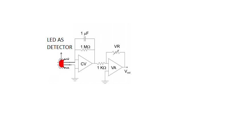
There is real problem here:
assume that the current through LED is −0.1µA, VR=10kOhm, then Vout
should be 1V but the actual reading is 1.303 for example.
Apparently you "assume" the current is 0.1 uA, but you measure the output voltage at 1.303.
Unless you measure the current as being 0.1 uA, there is no way to tell if it really is. Then you have no way to tell that the output is actually wrong.
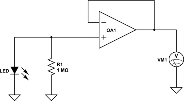
I'd suggest building the following circuit

simulate this circuit – Schematic created using CircuitLab
Here the critical parameter to consider is the input bias current current of the op amp. Make sure that it is on the order of 1 nA or less. Also fairly important is the input offset voltage. Since the nominal voltage across the resistor will be about 100 mV for an assumed LED current of 0.1 uA, you'll want an offset of 1 mV or less if you want 1% accuracy.
With this circuit, you can establish the actual current being provided. Only then can you start determining what your system error actually is.
Note that this circuit essentially does the same thing as the TIA you built for the first stage, and doesn't have the possible stability issues which make the feedback capacitor necessary. So why use a TIA? It's faster for large gains. The feedback capacitor compensates for the LED capacitance which will limit the follower circuit.


