6
\$\begingroup\$

When a transformer has the secondary open and it's driven by an AC source, the only current that the primary draws is the current needed to produce the flux to magnetize the core (like ferrite) of the transformer.

Then we put a load on the secondary, that is, a resistor across the secondary coil. Now the primary draws more current: Let's say this is a step-up transformer, so we know that the voltage across the secondary coil is some multiple of the voltage across the primary coil. To get the current on the secondary, we divide the stepped-up voltage by the resistance of the resistor. To preserve energy, the primary must now draw more current to make the power (product of voltage and current) the same on both sides.

But what is the actual physical mechanism (for the lack of a better word) why this extra current must be drawn by the primary? I mean, the nature doesn't know that we have a law of energy conservation, or that the product of voltage and current must be the same on both sides.

I suppose this has something to with fluxes. The magnetizing current sets the flux that puts the stepped up voltage across the secondary coil. This voltage causes current to flow on the secondary. This current oscillates and passes through the secondary coil, therefore producing magnetic flux. Now the core has flux from the magnetizing current and from the bigger current now flowing in the secondary. So apparently now the primary "wants to" combat this flux from the secondary with a flux of it's own, therefore "pushing" more current (more than the initial magnetizing current) through it's own coil (the primary coil of the transformer). I also understand why it makes sense that the current ratio is the same as the coil ratio: If the secondary has more turns, the primary needs more current to produce the same flux as the secondary (secondary has more turns so with smaller current the magnetic fields from all turns add).

I'm also familiar with the equivalent model of the transformer and how the ideal transformer differs from a real one. Looking at the equivalent model has not helped me. So what is the physical reason why more current "has to" flow into the primary when current is drawn from the secondary?

\$\endgroup\$
9
  • 1
    \$\begingroup\$ Have you heard of Maxwell equations? Well, they are way more abstract than the "actual physical mechanism"... \$\endgroup\$
    – Eugene Sh.
    Commented May 1, 2017 at 18:53
  • 3
    \$\begingroup\$ I would say that because of nature we have a law of energy conservation. \$\endgroup\$
    – Tyler
    Commented May 1, 2017 at 18:55
  • \$\begingroup\$ Yeah, that's a funny statement. It's like there wasn't this law in the nature before discovered... That's it, discovered. Not invented. \$\endgroup\$
    – Eugene Sh.
    Commented May 1, 2017 at 18:57
  • \$\begingroup\$ @Tyler Exactly my point! \$\endgroup\$
    – S. Rotos
    Commented May 1, 2017 at 18:59
  • 1
    \$\begingroup\$ "I mean, the nature doesn't know that we have a law of energy conservation, ..." You have a fundamental misunderstanding here. The law of energy conservation IS nature's law. It has never been observed to be violated. \$\endgroup\$
    – Dave Tweed
    Commented May 1, 2017 at 19:29

6 Answers 6

2
\$\begingroup\$

I think there is a simpler mechanism that nobody has mentioned. If a current starts to flow through the secondary winding than that current produces an opposing magnetic flux (according to the law of induction).

When this is the case the magnetic flux in the iron core weakenes. This also means that less voltage is induced in the primary winding (again refer to the induction law). As a consequence the voltage difference between input and the primary induced voltage rises which means more current starts to flow from the "source" and of course through the primary.

\$\endgroup\$
3
  • \$\begingroup\$ Wrong! The magnetic flux only reduces because of the leakage inductances and resistances slightly lowering the voltage that appears on that part of the primary that 100% couples to the secondary. In a perfect transformer that has no leakage, the flux remains constant and the secondary load ampere turns are exactly equalled and opposed to the load ampere turns referred to the primary - net effect - same flux. What you hear when the secondary isn't loaded is a slight increase in core saturation because there is barely any volt-drop across the primary leakage components hence a bit more flux. \$\endgroup\$
    – Andy aka
    Commented Jun 4, 2017 at 19:48
  • \$\begingroup\$ So ask yourself why nobody has mentioned this. \$\endgroup\$
    – Andy aka
    Commented Jun 4, 2017 at 19:50
  • \$\begingroup\$ OK, so I was wrong about flux lowering because of increasing load. But I still don't see what is wrong with the explaination that a secondary current induces an opposing voltage in the primary which makes more primary current to flow. After a transient the flux is returned to the previous amplitude (as long as the transformer is perfect). \$\endgroup\$ Commented Jun 5, 2017 at 6:26
1
\$\begingroup\$

Think about two very closely positioned loops of wire. If you apply an ac voltage to one loop, the induced voltage on the other loop would be the same. If a load on the second loop took current, the voltage won't change because the two loops are so physically close. If the voltage doesn't change under load, then the magnetic flux that couples both coils must remain constant. That's Faraday's law of induction in action and it is absolute key in understanding this problem.

If (as a thought experiment) the flux had increased, this would produce more secondary voltage and therefore more current and therefore more flux and this spirals out of control. This can't happen! Faraday's law holds.

So, in short, the primary takes an extra current whose flux exactly cancels the flux produced by current in the secondary leaving, just the magnetisation flux.

The load fluxes cancel because these extra currents are the same magnitude but acting in opposite directions. When you have a step up or step down transformer it is the ampere-turns (magneto motive forces) that are the same but, for a simple 1:1 situation it's easier just to talk in amps rather than ampere-turns.

\$\endgroup\$
0
1
\$\begingroup\$

This is the way it was taught to me and is, in my mind, fairly easy to understand.

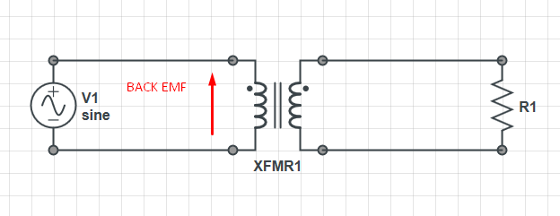
Consider the transformer circuit below.

enter image description here

A magnetic field is generated by the source. That field effectively creates a back EMF across the primary. In an ideal transformer, with no load on the output, when the field is string enough that back EMF cancels the applied voltage so no current can flow.

When a load is applied, the current taken by the load tries to change the field in the transformer. The change in field in turn reduces the back EMF on the primary. There in now an imbalance in voltages on the primary side, so current will flow from the source to sustain the transformer field.

The ratio of how much the load current tries to change the field to how much the supply needs to apply to fight it is governed by the turns ratio. The energy expended on both sides being equal.

In many ways, a transformer is a true flux capacitor.

Of course all this happens at light speed and sub-atomically and the net macroscopic effect on the transformer flux is zero measurable change.

EDIT: I see a few negative responses to this answer which I am sure are being generated either by my poor writing or by stoic adherence to Savart, Maxwell and Faraday's definitions. That is fine. However I'd like to point out that the latter equations and theories relate to the macroscopic measurable effects not the quantum and time dependent effects at the atomic level. There is interesting literature out there on Perturbation Theory and in particular Reconstruction of Macroscopic Maxwell Equations: A Single Susceptibility Theory

EDIT 2:

Since I don't think I explained my model very well I'd like to show you it in a different way.

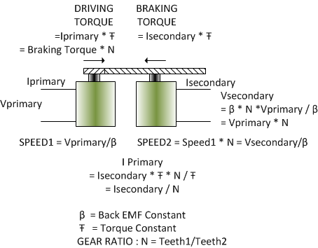
For the moment, lefts take flux out of the picture. This example breaks the transformer into two ideal and equal motor/generators locked together by gears as shown below.

enter image description here

The coils in the primary now spins a rotor, which in turn spins an equivalent rotor in the generator. The speed of the motor is governed by the Back EMF Constant, and in an ideal motor will self regulate to that voltage.

As you can see, the output voltage follows the same formula as that of a transformer that is, \$V_{Secondary} = V_{Primary} * N\$.

When current is drawn from the secondary it applies a braking torque to the generator. In order to maintain the regulated speed, the motor MUST apply the same torque to balance that braking torque. The motor must therefore consume the appropriate amount of current to generate that torque.

Again the formula for that current transfer follows the traditional transformer equation of \$I_{Primary} = I_{Secondary} / N\$.

As such you can see the above model accurately represents how we understand a transformer to work.

Of course a transformer does not quite work that way since the above implies it would work in DC. This model really needs to be extended to make the primary motor an ideal rotary voice coil where it's Back EMF Constant is measured in Volts Per Degree of Rotation, however the math still works out the same.

In an actual transformer the same thing is happening, only the motions are taking place at the atomic level as electrons and atoms re-arrange themselves in the dance that is electromagnetism.

\$\endgroup\$
19
  • 1
    \$\begingroup\$ The current taken by a resistor on the secondary is at 90 degrees to the primary mag current therefore it cannot cancel it. Be careful about dumbing this down too much Trevor. \$\endgroup\$
    – Andy aka
    Commented May 1, 2017 at 19:16
  • \$\begingroup\$ @Andyaka yup, I know, good add. I didn't want to go there lest it muddy it though. Principal is the same though. flux imbalance. Distort may have been a better word. \$\endgroup\$
    – Trevor_G
    Commented May 1, 2017 at 19:20
  • \$\begingroup\$ I'm sorry but i have to downvote - there is too much myth in this answer for instance, "the current taken by the load tries to change the field in the transformer" - no it doesn't, the field that couples primary and secondary is not altered one bit in a perfect transformer and, for most practical occasions this is also very true (in fact on heavy loads, imperfect transformers tend to reduce magnetization current). \$\endgroup\$
    – Andy aka
    Commented May 1, 2017 at 19:38
  • 2
    \$\begingroup\$ @Andy, I said it TRIES... man, it's cause and effect, it all happens at sub-atomic and light speed levels, but it all happens. You see no change at the macroscopic level, but that's the mechanism just the same. Things do not happen by magic. \$\endgroup\$
    – Trevor_G
    Commented May 1, 2017 at 20:39
  • 2
    \$\begingroup\$ @Andyaka nope I stand by that. Like it or not, it takes a finite time for the effect of the load to ripple back to the primary. \$\endgroup\$
    – Trevor_G
    Commented May 1, 2017 at 21:08
0
\$\begingroup\$

But what is the actual physical mechanism (for the lack of a better word) why this extra current must be drawn by the primary?

The energy put into the coil can creates a magnetic field. If this coil were alone that's all it would do. Because there is another coil, the magnetic field does work (transfer of energy) on the electrons in the secondary and can create a voltage (to do more work in another part of the circuit). However, if there is no load on the secondary then no work is being done and the electrons don't move. Voltage is still created but it's as if the secondary isn't there and the transformer behaves more like an inductor, only generating a magnetic field.

So what is the physical reason why more current "has to" flow into the primary when current is drawn from the secondary?
Because the electrons in the secondary are under the influence of a magnetic field, they want to move. This will create a voltage (and current). The models neglect the magnetic field (usually) because most time series simulations only use voltage and current, calculating the magnetic field is unnecessary for most people.

Coils, turns and other variables are just ways to simplify what is really going on. Each moving charge carrier (electron) creates a magnetic field and that magnetic field can move other electrons. Since we don't want to calculate the field for every charge, we use vector calculus to simplify this process with these laws: Biot Savart and Maxwell's Equations and Faradays law of induction. These are then simplified to come up with the transformer equations

\$\endgroup\$
2
  • \$\begingroup\$ You say: "Because the electrons in the secondary are under the influence of a magnetic field, they want to move. This will create a voltage"...... I wish to point out that with an open circuit secondary winding, there is a secondary voltage but it is present without the movement of electrons. Can you shed some light please? \$\endgroup\$
    – Andy aka
    Commented May 2, 2017 at 7:17
  • \$\begingroup\$ Sure can. There is still a voltage created and some electrons moving through the air. :) No really, I'll edit the question \$\endgroup\$
    – Voltage Spike
    Commented May 2, 2017 at 15:31
-1
\$\begingroup\$

Let's talk ideal transformer since you are trying to get a concept. With the secondary open no current in the secondary means no magnetic field created in the secondary. In the primary the magnetic field created opposes, according to lenz's law, the source that caused it. In essence a voltage is induced that opposes the source. This keeps the current small. Now when you add the load, current can flow in the secondary. This produces a magnetic field in the secondary winding. Again Lenz's law says this will oppose the changing field that caused it. That means it is opposing the primary field. This reduces the emf in the primary which allows more primary current to flow. This is very simplified, but I hope it will help you see it.

\$\endgroup\$
11
  • \$\begingroup\$ Of course there is a magnetic field in the secondary - how will you induce a voltage in it without one? \$\endgroup\$
    – Andy aka
    Commented May 2, 2017 at 9:04
  • \$\begingroup\$ If the secondary is open, no current flows in the secondary. Yes the field from the primary cuts the secondary but with no current in it doesn't produce a field that opposes the primary. If you don't understand this, I think you are a little out of your element. \$\endgroup\$
    – owg60
    Commented May 2, 2017 at 11:02
  • \$\begingroup\$ I think you need to re-read what you have said in your answer. \$\endgroup\$
    – Andy aka
    Commented May 2, 2017 at 11:03
  • \$\begingroup\$ AA, Do you think only the primary creates flux when the secondary is loaded? \$\endgroup\$
    – owg60
    Commented May 2, 2017 at 11:08
  • \$\begingroup\$ Any current in the secondary is matched by a current in the primary that keeps the core flux at precisely what the core flux was when there was no secondary current. Ampere turns in the secondary (due to a load) are equal and opposite to ampere turns in the primary that are due to that secondary load. No net flux increase or decrease. \$\endgroup\$
    – Andy aka
    Commented May 2, 2017 at 12:07
-1
\$\begingroup\$

In my short schooling, I have learned about Maxwell, and Faraday's laws and equations, but fail to see anybody mention the effects of transformer losses like primary winding resistance/leakage, the effects of eddy currents within the core on the primary (as the primary charges/changes flux in the core). One person did mention air resistance between the open secondary ends, but failed to mention that the secondary also would experience a minuscule load from it's own winding resistance and insulation leakages.

All these imperfections could be accounted for and would explain why the primary still draws at least some current, even with an open secondary. Forgive me if this is more of a philosophical answer than a hard fact one filled with calculus. Electronics is more a passion than a profession for me. (22yrs as collision frame tech)

\$\endgroup\$

Your Answer

By clicking “Post Your Answer”, you agree to our terms of service and acknowledge you have read our privacy policy.

Not the answer you're looking for? Browse other questions tagged or ask your own question.