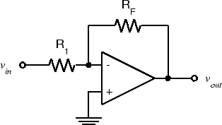
Below is a typical inverting op amp topology:
I was about to answer to this question, but I wasn't sure about the conclusion and couldn't find a supporting document so far.
Normally in tutorials they explain the input impedance of this topology simply as:
Rin = R1.
This is because the voltage at the inverting input is "approximately" zero, so one can say: I = (Vi - 0)/Rin . This looks like an approximation neglecting the effect of Rf.
I'm trying to derive the input impedance in terms of feedback equation to see the effect of Rf.
Calling "a" as the open loop gain.
Ir=If=I
Vo = -a*Vd
Vd = (Vi-I*R1-0)
Vo = Vi-I*(Rf+R1)
-a*(Vi-IR1) = Vi-I(Rf+R1)
Vi(1+a) = aIR1 + I*(Rf+R1)
Vi(1+a) = I(a*R1+R1+Rf)
Vi/I = (R1*(1+a) + Rf) / 1+a
Rin = Vi/I = R1 + (Rf / 1+a)
So is the equation Rin = R1 + (Rf / 1+a) correct?


Rin+Rf/(1+a), and again assuming an ideal opampais infinite, so R1 = Rin. \$\endgroup\$