0
\$\begingroup\$

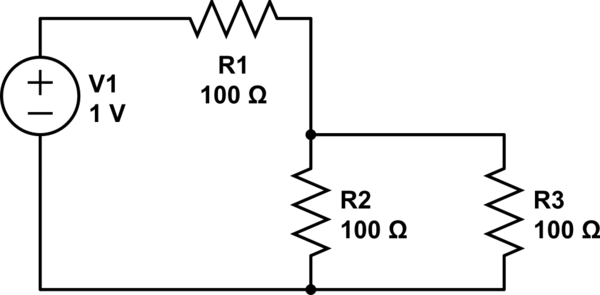
Example circuit has a voltage source, and 3 resistors.

When constructing Thevenin equivalent circuit, the voltage source is replaced with a short, while R1 & R2 resistance is calculated as though they were in parallel, even though in original circuit they were in series.

Why?

When using Thevenin's theorem to calculate current and voltage of R3,
schematic

simulate this circuit – Schematic created using CircuitLab

\$\endgroup\$

1 Answer 1

0
\$\begingroup\$

When calculating the Thevenin equivalent resistance, you're asking, if the current out the output port changes, how much will the voltage across it change.

So you can think of it like a superposition problem with a hypothetical current source connected to the output port. When calculating the effect of this source, you need to zero out the other sources in the circuit.

And when V1 is zero'd out (replaced with a short circuit) you'll see that R1 and R2 are connected in parallel.

\$\endgroup\$
2
  • \$\begingroup\$ Problem of course is that the output port isn't indicated on the schematic. \$\endgroup\$
    – Ben Voigt
    Commented May 6, 2017 at 17:38
  • \$\begingroup\$ R3 is replaced with the output port in the original example. \$\endgroup\$ Commented May 6, 2017 at 18:17

Your Answer

By clicking “Post Your Answer”, you agree to our terms of service and acknowledge you have read our privacy policy.

Not the answer you're looking for? Browse other questions tagged or ask your own question.