1
\$\begingroup\$

I'm doing a simple circuit using LM385. In THEORY voltage measured on cathode of D2 should be 5V. And it is so, if R2 and R3 are not present in the circuit. So voltage divider from R2 and R3 across voltage of 5V should give OUT voltage of 3.4V.

However when I measure it, OUT is only 2.5V and voltage measured on cathode of D2 is only 3.7V!

Could someone explain me please what am I missing?
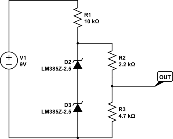
schematic

simulate this circuit – Schematic created using CircuitLab

\$\endgroup\$

6 Answers 6

1
\$\begingroup\$

The load current across the resistors parallel to the references, assuming you have 5 volts, is \$\frac {5V}{6.9k\Omega} =0.724mA \$. When you put that current through your \$10k\Omega\$ resistor, the voltage drop across that is 7.24 Volts. Add that to your 5Volts, and you have 12.24V, which you're trying to provide with a 9V battery. This, of course, ignores your bias current through your LM385-2.5's.

You can't do this with one 9V battery. You need to drop the 10K to a lower value, or use two batteries, but make sure you don't exceed the maximum bias currents for your references.

\$\endgroup\$
1
\$\begingroup\$

D2 and D3 cannot magically make 5 volts appear at the junction of R1 and R2 if the basic voltage at the point is less than 5 volt when D2 and D3 are not present. Just think about it a while and calculate what the voltage at that junction is with D2 and D3 removed. Then the curtain will rise.

\$\endgroup\$
1
\$\begingroup\$

OK without the two resistors the max current that can flow through R1 is

\$9v-5v/10,000 = 0.4mA\$

However, the \$R2 + R3\$ chain want to draw \$5v/69,900 = 0.724mA\$

So, as you can see, R1 needs to be a lot smaller.

Those references are not batteries. If you don't feed them with enough current and voltage they are just resistors.

\$\endgroup\$
1
  • 1
    \$\begingroup\$ Great! I changed R2 and R3 to 47k and 22k and all works fine! \$\endgroup\$
    – Em Ka
    Commented May 9, 2017 at 14:56
0
\$\begingroup\$

The circuit operates as a resistive voltage divider. To achieve the desired result descending resistance R1. Or increase the total resistance R2 + R3.

\$\endgroup\$
4
  • \$\begingroup\$ I don't understand what you mean by resistive voltage divider - could you please explain? \$\endgroup\$
    – Em Ka
    Commented May 9, 2017 at 14:22
  • \$\begingroup\$ Besides, from what I understand voltage across anode of D1 and cathode of D2 should be always 5V, right? \$\endgroup\$
    – Em Ka
    Commented May 9, 2017 at 14:23
  • \$\begingroup\$ @Em Ka I mean Voltage divider / Resistive divider \$\endgroup\$
    – AltAir
    Commented May 9, 2017 at 14:26
  • \$\begingroup\$ @Em Ka, D2 and D3 'start working' when the voltage is higher to 5V in. When the voltage is less than 5V they can be neglected. As if they are not. \$\endgroup\$
    – AltAir
    Commented May 9, 2017 at 14:30
0
\$\begingroup\$

Select a lower value for R1. Try with 1k.

The problem you're encountering is that R1 is so high that it doesn't let enough current flowing through to operate the diodes as they should.

The R2 + R3 divider alone will draw 0.725 mA at 5V. The diodes need, according to the datasheet, a minimum of 20 uA to operate. That adds up to a minimum of 0.745 mA through R1.

However, at 4V voltage drop, the 10k resistor can only provide 0.400 mA, which is insufficient. The maximum value of resistor R1 for this circuit to work as intended is 4 V / 0.724 mA = 5.5 k. You must select a value well below this.

\$\endgroup\$
-1
\$\begingroup\$

schematic

simulate this circuit – Schematic created using CircuitLab
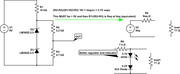
Even better, use a 18650 LiPo cell at 3.6V

\$\endgroup\$
1
  • \$\begingroup\$ what don't U understand ? -1? \$\endgroup\$
    – D.A.S.
    Commented May 9, 2017 at 16:03

Your Answer

By clicking “Post Your Answer”, you agree to our terms of service and acknowledge you have read our privacy policy.

Not the answer you're looking for? Browse other questions tagged or ask your own question.