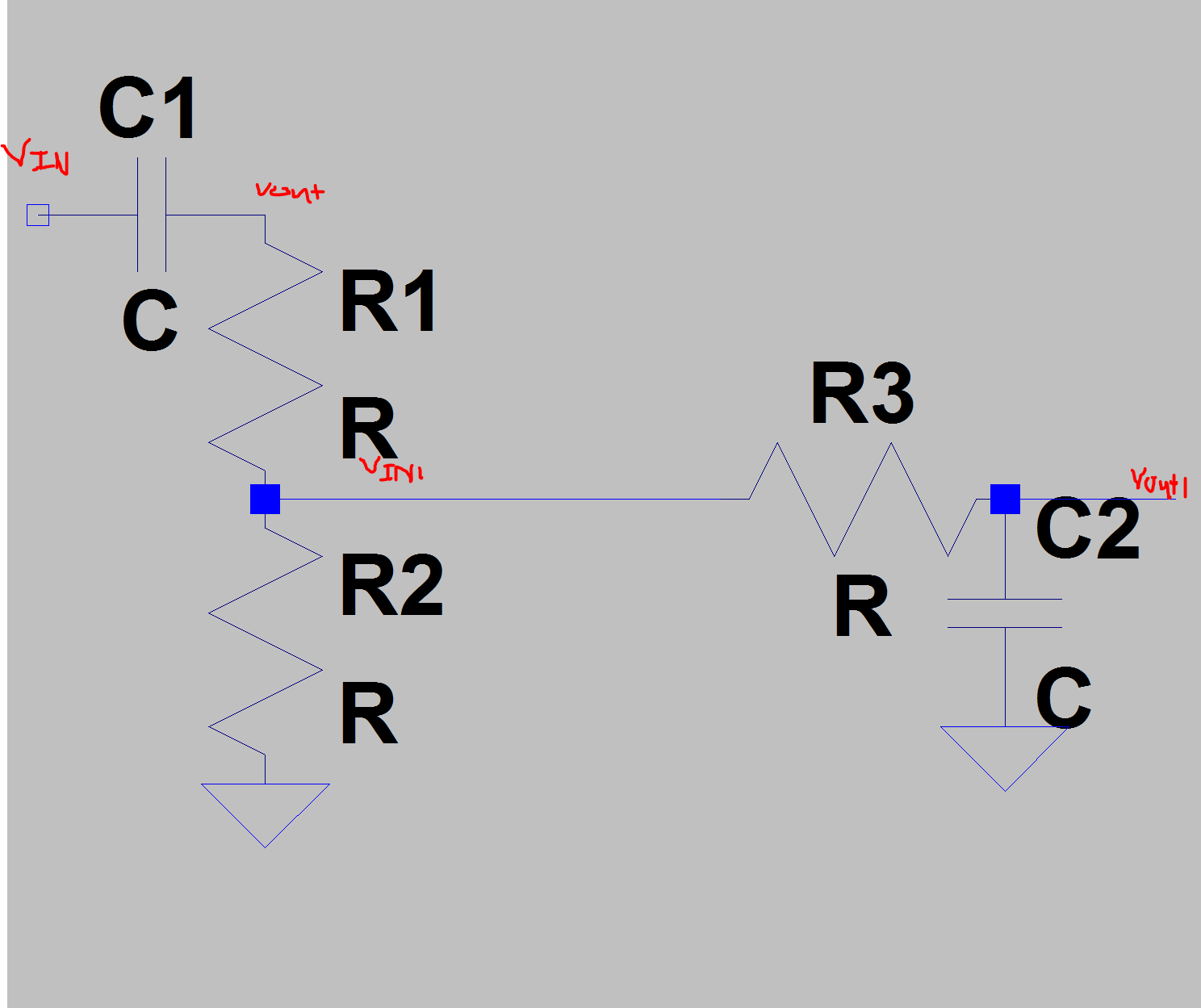
For the following circuit i am having trouble finding the following respective cutoff frequencies as i am unsure on if i need to take in to account R3 for the high pass portion. Also for the low pass portion do i need to take into account R1 and R2 or not as i know what Vin1 will be?
R1 and R2 are used as a voltage divider as Vout1 has to be less than a certain voltage due to the use it entering an amp after.
Hence what are the formulas i need to use to calculate the cutoff frequencies for say 15Hz - 50kHz? Can i just do for the highpass fc=1/(2pi*(R1+R2)*C) and for the lowpass portion fc=1/(2*pi*R3*C)? To find Vout1 can i just do Vin1*(R/(R+1/jwc))?
Also the high pass is used to block the dc bias from the input.
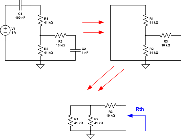
Also so are R1 and R2 in series? Then if they are what is R3 in terms of R1 and R2 (as in parallel OR series configuration)
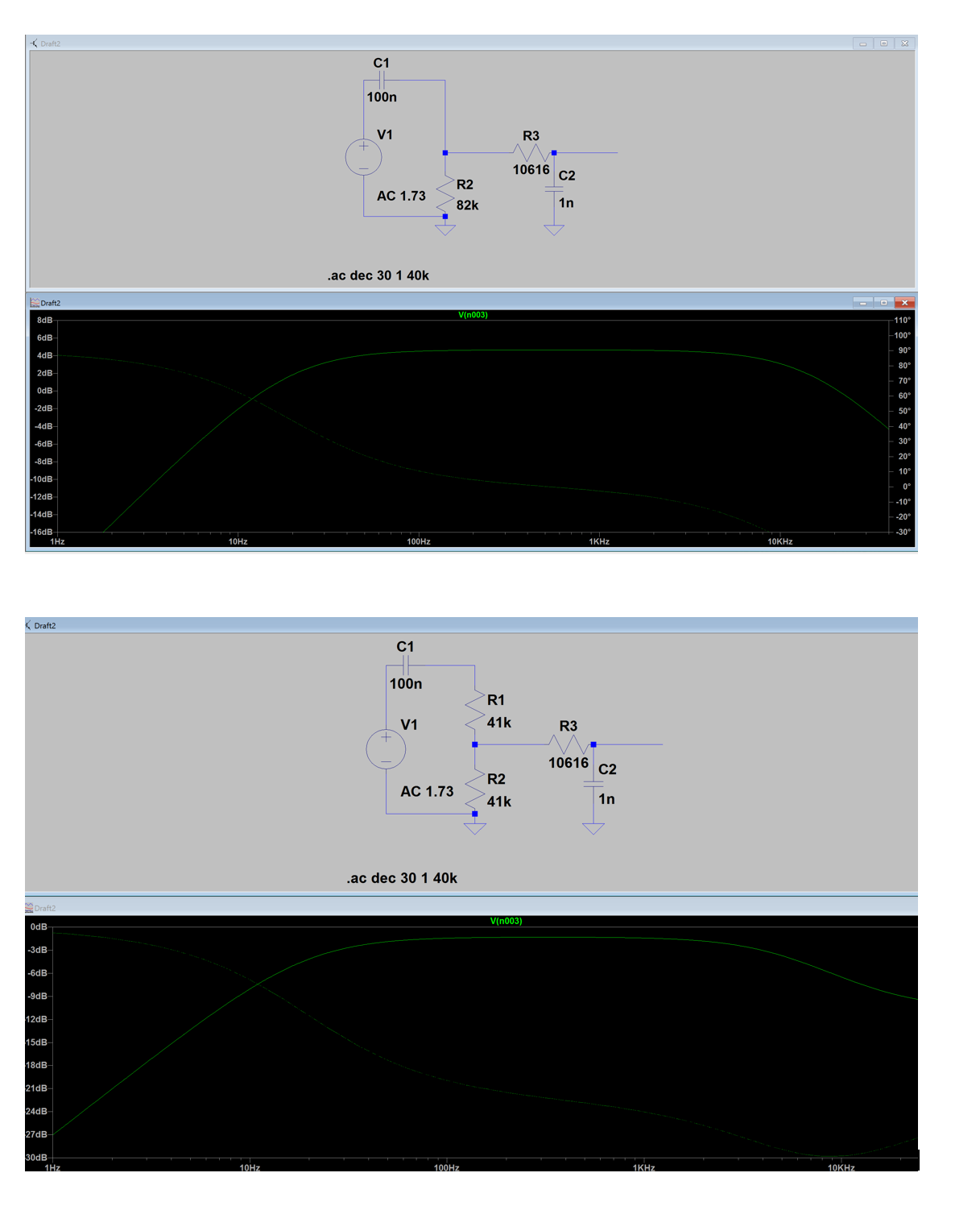
UPDATED: For this given example when i analyse it like the the first plot it gets the correct cutoff frequencies that i am expecting. The problem is that i dont get how to calculate the resistor values for when the voltage divider is used. As it can be seen when i tried, the cutoff frequencies are not what i want and are far off. Hence what equations do i use to calculate R1,R2 and R3 as i assume for the second plot all resistors matter for each filter.
First plot gets 20Hz and 15kHz for the -3db cutoff however the second plot is around 20Hz and 5kHz?
Thus how i calculated the lowpass resistor value is wrong and was wondering what formula is needed for fc for the lowpass.

