5
\$\begingroup\$

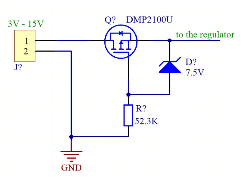
I have such a reverse polarity protection circuit for the power supply:

Reverse polarity protection circuit

The MOSFET used has a maximum VGS of 10 V, so that's why there's a Zener diode of 7.5 V.

But what happens if I connect, let's say, 12 V? I don't fully understand how this Zener diode is working.

  • It will start to conduct from 7.5 V.
  • So from 12 V it will "conduct 4.5 V" to the gate.
  • So the voltage on the gate relatively to the ground will be +4.5 V.
  • But the voltage on the gate relatively to the source (VGS) will be -7.5 V (4.5 V - 12 V).
  • This MOSFET needs around -2 V to start to conduct. It gets -7.5 V, so is that why it's working?

Am I correct with this? Do I understand this properly?

\$\endgroup\$

2 Answers 2

7
\$\begingroup\$

If you suddenly connect +12 to the input, the source will immediately rise to +11.3 or so because of the body diode conducting.

The gate will charge towards -11.3V with respect to the source through R?. When the gate reaches the threshold voltage the MOSFET channel will begin to conduct, and by the time the gate-source voltage reaches a few volts the MOSFET channel will be conducting almost all the current, the output voltage will be close to +12V. It continues to charge until it reaches about -7.5V at which point the Zener diode begins to shunt significant current away from the gate.

In steady state with 12V in the gate sits at -7.5V with respect to the source, and the MOSFET happily conducts in the reverse direction to normal.

Edit: Regarding the Zener gate protection I would like to graft a comment below into this answer

You could replace the zener+resistor with a direct connection if you are sure there are no transients. Or with a resistor if the gate is already protected adequately internally. Or a divider under similar conditions. There is a vulnerability whenever a resistor is used in the pathological case where the supply is suddenly reversed (or, less pathologically, connected to AC) because the MOSFET gate charge may not have enough time to bleed off and the circuit downstream will get a nasty pulse at reverse polarity.

\$\endgroup\$
7
  • 1
    \$\begingroup\$ Well, that's the analysis of the circuit. But the reason I believe is that the source-gate voltage must not go beyond a certain value (otherwise the transistor would become damaged); the Zener ensures that 7.5V is the maximum Vgs difference, while "R?" makes it so the gate voltage is as low as possible (which is <7.5V). You could replace the zener with a simple resistor instead if your voltage range/budget allows it, depending on the FET characteristics. \$\endgroup\$ Commented May 16, 2017 at 12:39
  • \$\begingroup\$ Side question: can this circuit also be used instead of Schottky diode when connecting few power supply sources into one? \$\endgroup\$
    – zupazt3
    Commented May 16, 2017 at 13:22
  • 1
    \$\begingroup\$ @GuillermoPrandi Yes, that is the purpose of the Zener. You could replace the zener+resistor with a direct connection if you are sure there are no transients. Or with a resistor if the gate is already protected adequately internally. Or a divider under similar conditions. There is a vulnerability whenever a resistor is used in the pathological case where the supply is suddenly reversed (or, less pathologically, connected to AC) because the MOSFET gate charge may not have enough time to bleed off and the circuit downstream will get a nasty pulse at reverse polarity. \$\endgroup\$ Commented May 16, 2017 at 13:27
  • 1
    \$\begingroup\$ @zupazt3 It will not prevent current flowing in reverse (would actually be forward from the perspective of the MOSFET). There are circuits that will do what you suggest but they are fairly complex- LTC makes some (not cheap) ICs that encapsulate the circuitry. \$\endgroup\$ Commented May 16, 2017 at 13:28
  • \$\begingroup\$ @SpehroPefhany I hadn't think about the AC/gate charge problem. Good tip! \$\endgroup\$ Commented May 16, 2017 at 16:51
0
\$\begingroup\$

Well - when reverse connected, you would STILL have the reverse leakage current flowing the Mosfet body diode - hopefully very small. Someone suggested the reverse current (at 24 v) through an SS34 or something similar Shottky might be 12mA - acknowledging they hoped they read the graph correctly - I suspect an error here, as at 25 deg C for an SS14 (1A, 40v) the (logarithmic) graph suggests nearer 0.05 mA at 24v - 12 mA seems massive. Rises as temperature increases.

\$\endgroup\$

Your Answer

By clicking “Post Your Answer”, you agree to our terms of service and acknowledge you have read our privacy policy.

Not the answer you're looking for? Browse other questions tagged or ask your own question.