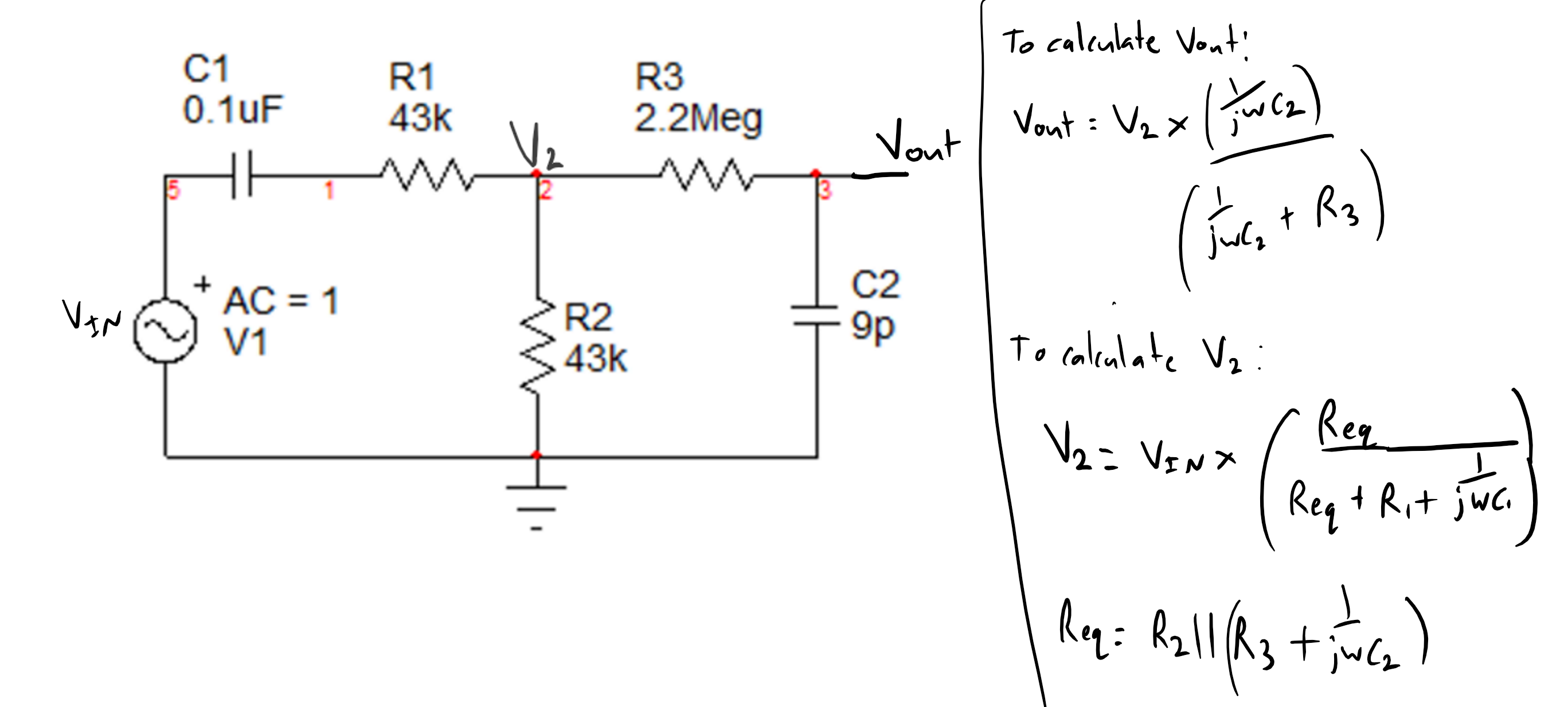
Hello for the following diagram below, i was just wondering if these formulas are correct to finding what they state (i.e. Vout and V2). For V2 is R3 and C2 in parallel with C2?
\$\begingroup\$
\$\endgroup\$
8
-
\$\begingroup\$ Looks good to me. \$\endgroup\$– Enric BlancoCommented May 16, 2017 at 7:07
-
\$\begingroup\$ It is interesting to realize that this procedure (calculate V2 and replace it by a ficticious voltage source V2) makes use of the "Substitution Theorem" of network theory (which is not very well-known). \$\endgroup\$– LvWCommented May 16, 2017 at 11:17
-
\$\begingroup\$ The correct answer is to find the thevin equivalent of looking into v2, then find vo, in your case because r3 is large you can approximate it this way. Or apply kcl.. \$\endgroup\$– sstobbeCommented May 16, 2017 at 11:31
-
\$\begingroup\$ for the frequency f to calculate the impedances it is the input signals frequency and not the cutoff frequencies correct? \$\endgroup\$– StudentCommented May 16, 2017 at 11:36
-
1\$\begingroup\$ Yes, f is the frequency of your input source \$\endgroup\$– sstobbeCommented May 16, 2017 at 11:40
|
Show 3 more comments
1 Answer
\$\begingroup\$
\$\endgroup\$
3
Those equations are correct, though clearly there is still additional working to get to your final answer.
-
\$\begingroup\$ for the frequency f to calculate the impedances it is the input signals frequency and not the cutoff frequencies correct? \$\endgroup\$– StudentCommented May 16, 2017 at 11:29
-
\$\begingroup\$ Yeah, the impedance of reactive components is a function of the driving frequency ie: the input frequency. \$\endgroup\$– espionnCommented May 16, 2017 at 12:25
-
\$\begingroup\$ Also remember that w is in radians per second, not hertz. \$\endgroup\$– espionnCommented May 16, 2017 at 12:26

