2
\$\begingroup\$

I came across this circuit as part of a larger circuit in a guitar effect pedal:
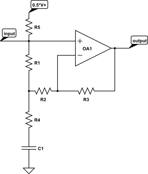
schematic

simulate this circuit – Schematic created using CircuitLab

I was wondering about the function of the resistor \$R_1\$. My calculations show that the same transfer function can be achieved with or without \$R_1\$ (leaving out \$R_1\$ just means that we need to change the other resistor values). The only difference that I can see is the change in input impedance of the circuit. Is this the only function of \$R_1\$ (i.e., reduce/define the input impedance), or is there anything else I'm missing?

\$\endgroup\$
10
  • \$\begingroup\$ Does your opamp have input bias current? \$\endgroup\$
    – sstobbe
    Commented May 20, 2017 at 15:35
  • \$\begingroup\$ @sstobbe: It's a real circuit with a real opamp, so yes, it does. I do not know exactly which type of opamp is used in the original circuit. \$\endgroup\$
    – Matt L.
    Commented May 20, 2017 at 15:38
  • \$\begingroup\$ R1 just biases input when not connected to a low R source to prevent noise. and gives low DC current. for AC coupled inputs. R1 is larger than all the others \$\endgroup\$
    – D.A.S.
    Commented May 20, 2017 at 15:41
  • \$\begingroup\$ If the input on the left is ac coupled you will have to provide a path for the DC bias current I'm not sure the approach taken is the best \$\endgroup\$
    – sstobbe
    Commented May 20, 2017 at 15:41
  • \$\begingroup\$ @TonyStewart.EEsince'75: The input of the circuit is connected to the output of another opamp (via an RC-low pass filter). Would your comment then still apply? \$\endgroup\$
    – Matt L.
    Commented May 20, 2017 at 15:46

1 Answer 1

1
\$\begingroup\$

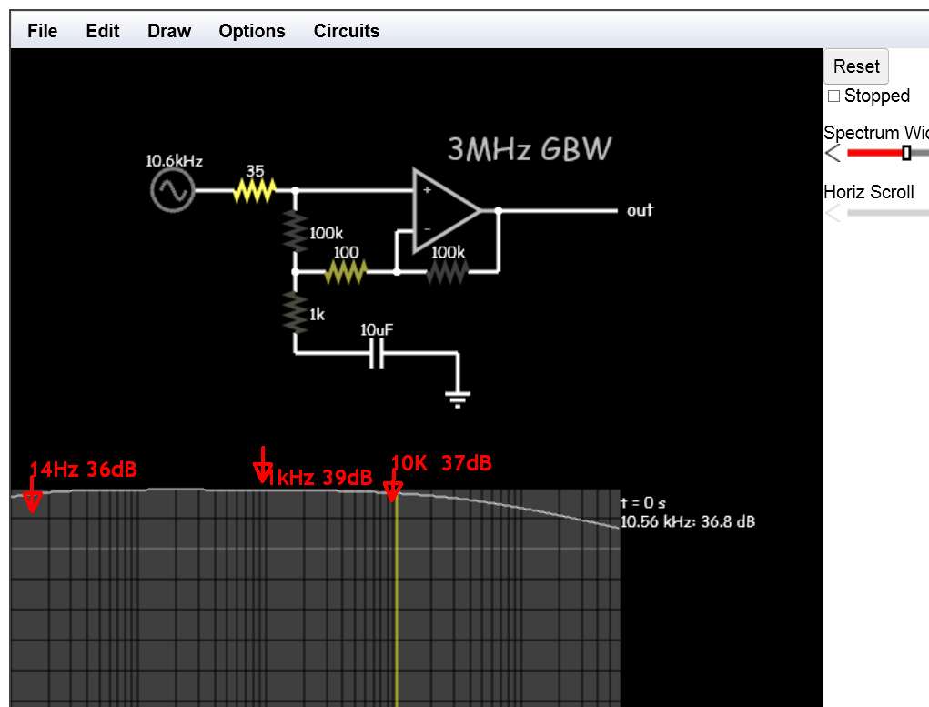
enter image description here

Reducing R1 from 100K to 1K lowers gain from 39dB to 38dB but reduces rolloff breakpoint to 8kHz. R1 also lowers input impedance so source impedance affects rolloff and gain is affected by source impedance if >= R1.

ADDITION of R5 makes R1 redundant and forces Vin to be AC coupled which affects HPF point and causes pop on plugin.

\$\endgroup\$
2
  • \$\begingroup\$ Thanks for your answer. So the conclusion is that R1 is actually redundant? That was also my first thought, but my circuit knowledge is a bit rusty. Note that this is part of a circuit in a commercial device which has been sold many times, so I wonder if/how there can be such a design flaw (if it actually is one). \$\endgroup\$
    – Matt L.
    Commented May 20, 2017 at 17:10
  • \$\begingroup\$ R5 makes R1 redundant since the DC voltage across +- inputs is always the same. whether biased to 0V for split supplies or V+/2 for single supply. Use the largest V+ avail. to prevent saturation, unless you like fuzz guitar and note GBW needed for gain used. I chose 3MHz min for gain of 100 to give 30kHz BW \$\endgroup\$
    – D.A.S.
    Commented May 20, 2017 at 18:23

Your Answer

By clicking “Post Your Answer”, you agree to our terms of service and acknowledge you have read our privacy policy.

Not the answer you're looking for? Browse other questions tagged or ask your own question.