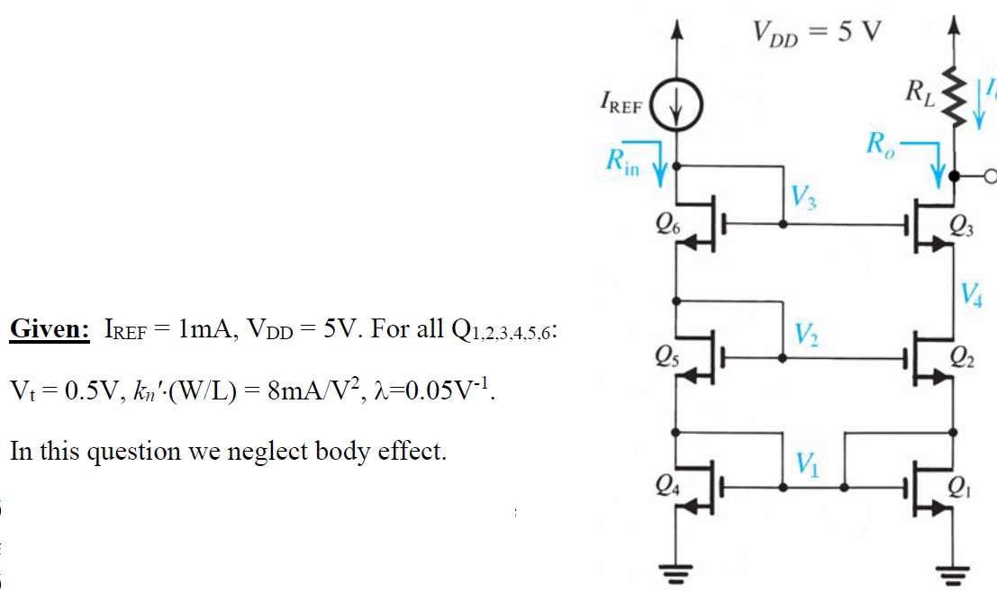
I was asked to determine the input resistance of the circuit in the figure, with and without channel effect. Is there a formula for that which could be applied or must I draw the small signal scheme and find it more rigorously?
-
\$\begingroup\$ Draw the small signal model and find each transistor state \$\endgroup\$– PDuarteCommented May 26, 2017 at 13:51
-
\$\begingroup\$ Input resistance, two series diodes + plus two parallel diodes (diodes = diode connected) \$\endgroup\$– sstobbeCommented May 26, 2017 at 14:40
-
\$\begingroup\$ Let me make sure I understand -- is the input resistance simply (1/gm4 || 1/gm1)+(1/gm5+1/gm6)? What about rds? Doesn't it play a role at all? Also, is the resistance of a diode connected CMOS 1/gm or is that merely its input resistance? If you don't mind addressing these queries.. \$\endgroup\$– peripateinCommented May 26, 2017 at 18:35
-
\$\begingroup\$ Aren't you just supposed to analyze this based on degenerative feedback and combined forward transconductance? (I'm just a hobbyist, but I find \$Q_1\$ and \$Q_4\$ an intriguing addition.) \$\endgroup\$– jonkCommented May 26, 2017 at 19:48
-
\$\begingroup\$ I am not sure.. Does the expression I wrote above make any sense? Is the input resistance really independent of rds? \$\endgroup\$– peripateinCommented May 26, 2017 at 19:57
1 Answer
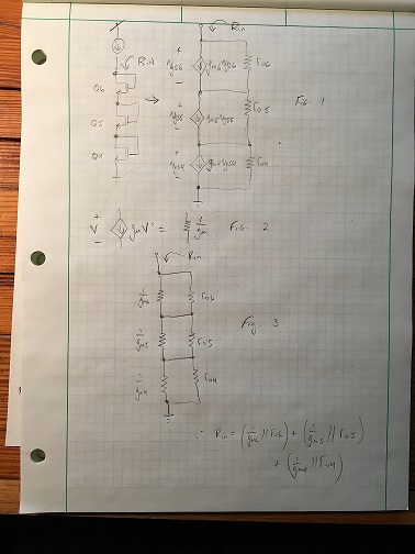
The key is to realize that any time you have a controlled current source whose output current value is proportional to the voltage applied across it -- that you can view this element as a resistor.
I've illustrated this in "Fig. 2".
Notice that when I apply a voltage "V" across my controlled current source, I get I = gmV.
Notice that when I apply a voltage "V" across a resistor of value (1/gm) I get a current I = V/(1/gm) = gmV.
Thus they are equivalent.
In Fig. 1 I've drawn the small signal model of the three diode connected devices. Notice that I've included ro. I've drawn the controlling voltage explicitly across each device to make the point that the equivalence of Fig. 2 holds.
Thus you can redraw the circuit as shown in Fig. 3. Usually we just approximate that a 1/gm in parallel to an ro is 1/gm since a small resistor in parallel with a big resistor looks like a small resistor.
I wouldn't normally draw the small-signal model but instead I'd just remember that a diode-connected MOSFET looks like an ro//1/gm.
-
\$\begingroup\$ Looks great, thanks! Based on this, does that mean that \$R_S\$ for Q2 would not be \$r_{o1}\$ but \$r_{o1} || 1/g_{m1}\$? Actually, I think it should be merely \$r_{o1}\$ as \$1/g_{m1}\$ would be in parallel to a short.. \$\endgroup\$ Commented May 27, 2017 at 16:58
-
\$\begingroup\$ Yes. The way I would approach finding "Rout" is to apply the expression given in your book (which I recognize is Sedra/Smith) for the output of a cascoded device. As an example, the output looking into the drain of Q1 would be ro2*gm2*Rs. Where Rs has the value you rightly pointed out. (The expresssion I've used for the output impedance of a cascode is a simplification, the full expression is given in your book, but I never remember it). Then you move up to Q3 and "look into" its drain and apply the same expression. \$\endgroup\$ Commented May 27, 2017 at 17:01
-
\$\begingroup\$ Wait, now I am confused -- didn't you intend to write "looking into the drain of Q2"? And is \$R_S=(1/gm1)||r_{o1}\$ or simply \$r_{o1}\$? \$\endgroup\$ Commented May 27, 2017 at 17:05
-
\$\begingroup\$ I meant looking into the drain of Q2. \$\endgroup\$ Commented May 27, 2017 at 17:08
-
\$\begingroup\$ But why isn't Q4 short circuiting 1/gm1? I mean, the way I see it since Q4 is considered ground 1/gm1 is in parallel to it and hence equals zero. Why is what I just wrote wrong? \$\endgroup\$ Commented May 27, 2017 at 17:11

